Catalyst Deterioration Detecting Apparatus of Vehicle Internal Combustion Engine

a technology of internal combustion engine and detecting apparatus, which is applied in the direction of electrical control, process and machine control, etc., can solve the problems of reducing the opportunity of calculating the oxygen storage capacity osc, deterioration of the drivability of the vehicle, and difficult to do away with the gap, so as to suppress the deterioration of the drivability

Inactive Publication Date: 2009-01-29
TOYOTA JIDOSHA KK
View PDF5 Cites 16 Cited by
  • Summary
  • Abstract
  • Description
  • Claims
  • Application Information

AI Technical Summary

Benefits of technology

[0012]Accordingly, it is an objective of the present invention to provide a catalyst deterioration detecting apparatus of a vehicle internal combustion engine which can suppress a deterioration of a drivability while ensuring opportunities of detecting a deterioration of an exhaust gas purifying catalyst.

Problems solved by technology

However, since the engaging portion and the engaged portion are manufactured in accordance with a machine work, it is hard to do away with the gap.
Accordingly, if the active air-fuel ratio control is executed by the catalyst deterioration detecting apparatus, there is a risk that the following problems are generated in the engaging portion and the engaged portion at a time when the target air-fuel ratio is inverted in correspondence to the inverse of the output of the oxygen sensor.
An abnormal noise and a vibration are generated in accordance with the contact and estrangement, and there is a risk that a deterioration of a drivability of the vehicle is caused.
However, this configuration reduces the opportunities of calculating the oxygen storage capacity OSC and detecting the deterioration of the exhaust gas purifying catalyst using the calculation in accordance with the inhibition of the active air-fuel ratio control.

Method used


Image

  • Catalyst Deterioration Detecting Apparatus of Vehicle Internal Combustion Engine
  • Catalyst Deterioration Detecting Apparatus of Vehicle Internal Combustion Engine
  • Catalyst Deterioration Detecting Apparatus of Vehicle Internal Combustion Engine

Examples


first embodiment

[0027]A description will be given of the present invention with reference to FIGS. 1 to 9.

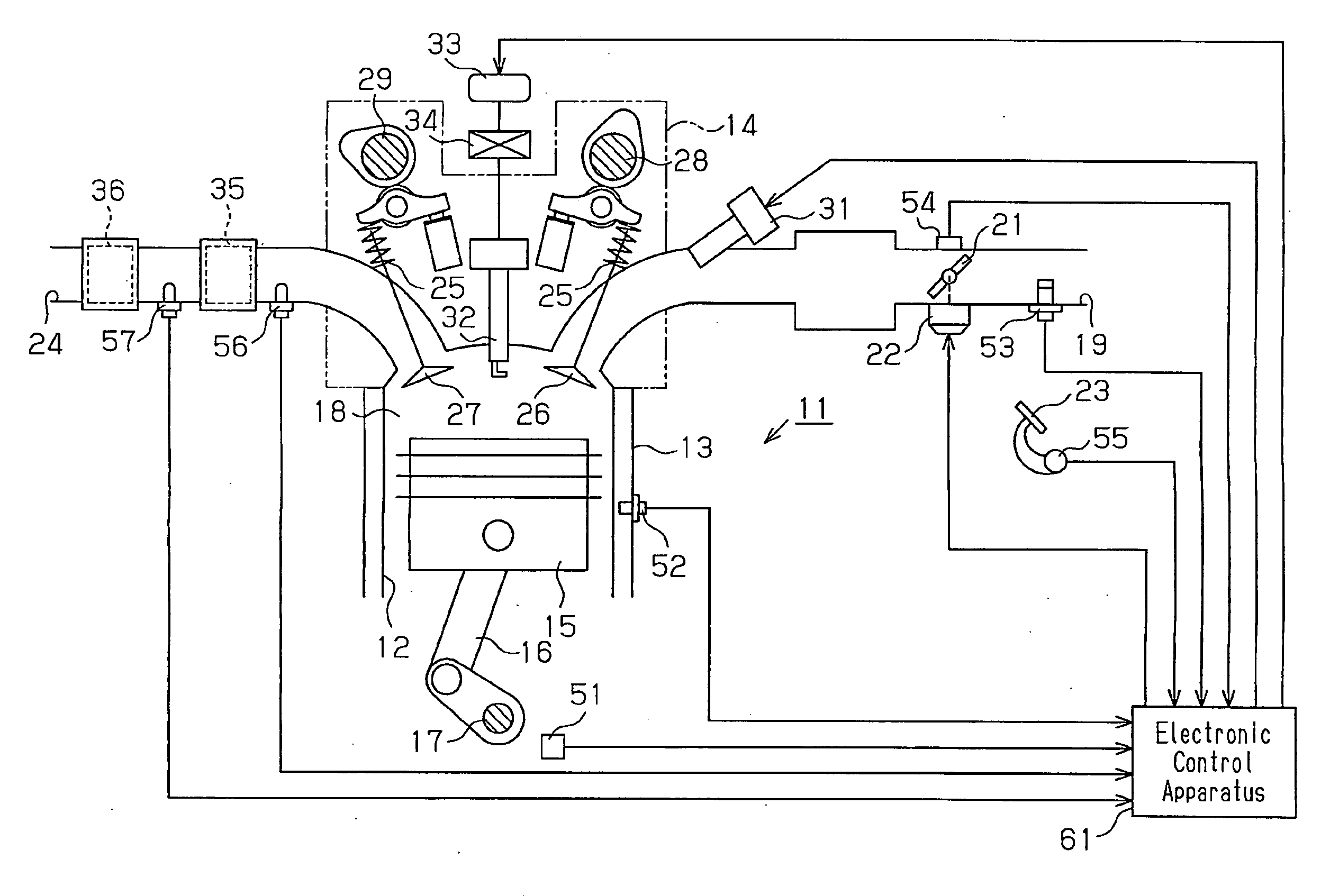
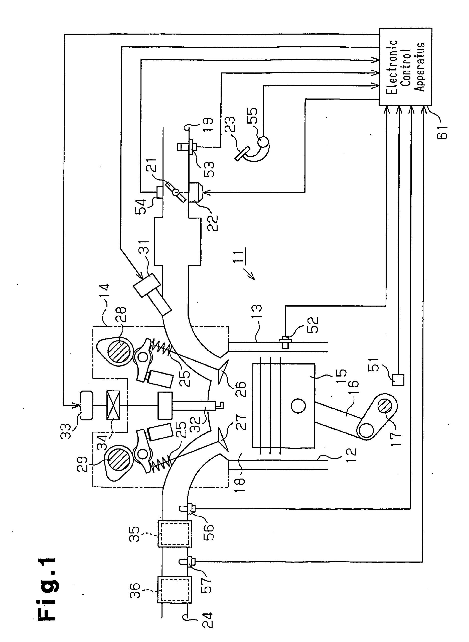
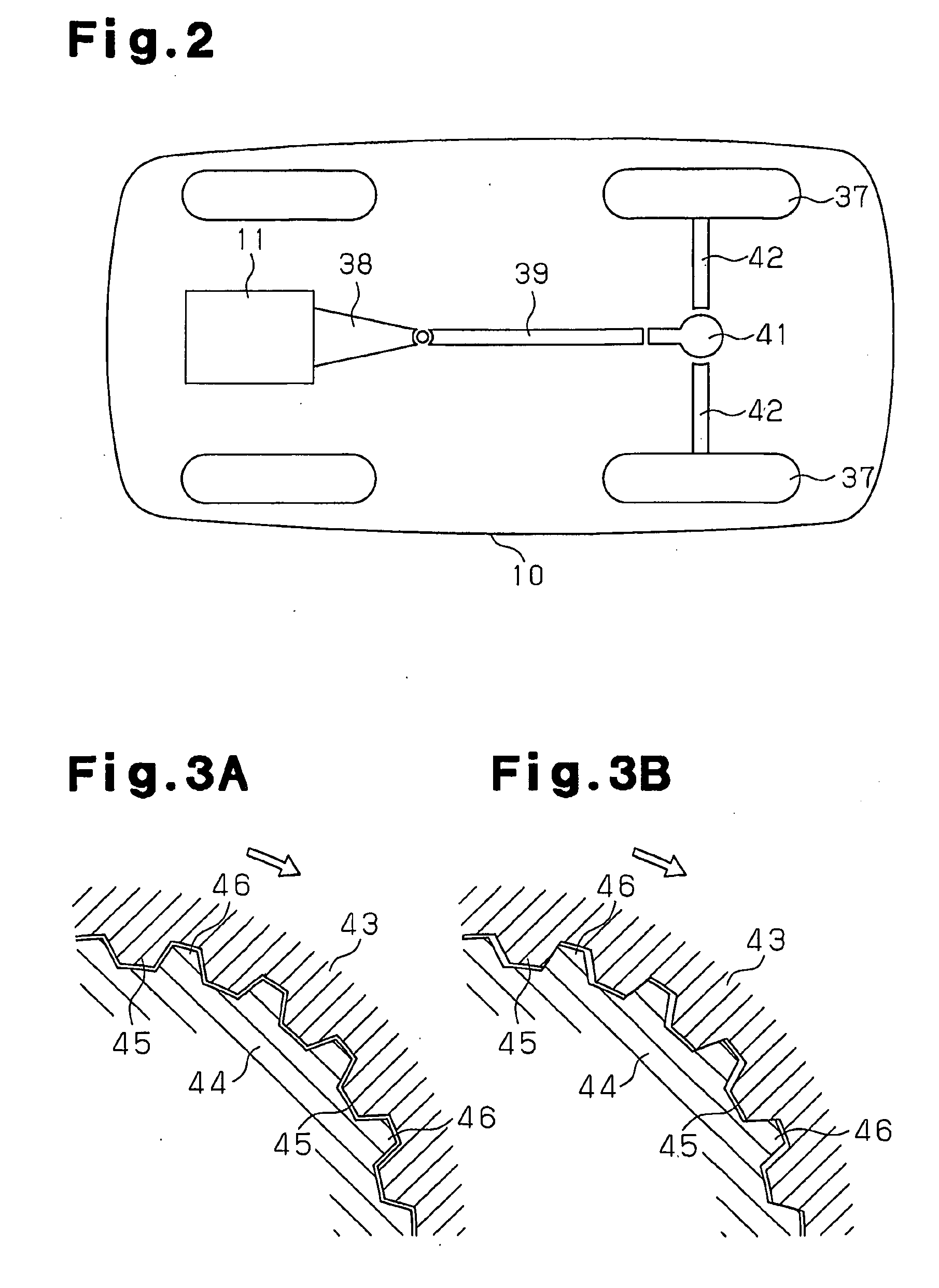
[0028]As shown in FIG. 2, an internal combustion engine 11, which is a gasoline engine, is mounted as a power source in a vehicle 10. As shown in FIG. 1, the internal combustion engine 11 is provided with a cylinder block 13 having a plurality of cylinders 12, and a cylinder head 14 mounted thereon. A piston 15 accommodated in each of the cylinders 12 is coupled to a crankshaft 17 corresponding to an output shaft of the internal combustion engine 11 via a connecting rod 16.

[0029]To a combustion chamber 18 in each of the cylinders 12 is connected an intake passage 19 for introducing air from the outside of the internal combustion engine 11 to the combustion chamber 18. A throttle valve 21 is pivotally provided in such a manner as to be rotated in the intake passage 19. An actuator 22 coupled to the throttle valve 21 is activated in correspondence to a pedaling operation of an accelerator pedal 2...


PUM


Abstract

A determining section integrates amount of oxygen that is stored in or released from a exhaust gas purifying catalyst from when a signal from an oxygen sensor is changed until when the signal is changed subsequently, thereby calculating an oxygen storage capacity. The determining section uses the calculated oxygen storage capacity to determine a deterioration state of the exhaust gas purifying catalyst. A limiting section sets, as an allowable change amount, a change amount of the air-fuel ratio that corresponds to an allowable maximum fluctuation amount of a torque of a output shaft of the engine. The limiting section limits a change of the target air-fuel ratio such that a change amount of the target air-fuel ratio due to a change of the signal does not exceed the allowable change amount. Therefore, a deterioration of a drivability while ensuring opportunities of detecting a deterioration of an exhaust gas purifying catalyst is suppressed.

Description

TECHNICAL FIELD[0001]The present invention relates to a catalyst deterioration detecting apparatus of a vehicle internal combustion engine which detects a deteriorated state of an exhaust gas purifying catalyst arranged in an exhaust passage of the vehicle internal combustion engine.BACKGROUND ART[0002]In an internal combustion engine mounted in a vehicle, a purification of exhaust gas components is generally executed by an exhaust gas purifying catalyst arranged in an exhaust passage. The exhaust gas purifying catalyst has an oxygen storage capacity OSC, and can store oxygen in a range of the oxygen storage capacity OSC. In the case that an unburned components such as hydro carbon (HC), carbon monoxide (CO) or the like is contained in the exhaust gas, the exhaust gas purifying catalyst oxidizes the unburned component by releasing the stored oxygen. Further, in the case that oxygen, nitrogen oxide (NOx) or the like is much contained in the exhaust gas, the exhaust gas purifying cata...

Claims


Application Information

Patent Timeline
Patent Type & Authority Applications(United States)
IPC IPC(8): F02D41/04G01M15/10
CPCF01N3/0864F01N3/101F01N11/007F01N2550/02F01N2560/025F01N13/0093F01N2570/16Y02T10/47Y02T10/22F01N13/009F01N2560/14Y02A50/20Y02T10/12Y02T10/40
Inventor MITSUTANI, NORITAKE
Owner TOYOTA JIDOSHA KK
Why Eureka
Try Eureka