AC magnetic tracking system with phase locking

a magnetic tracking and phase locking technology, applied in the field of magnetic tracking systems, can solve the problems of main and marker components interfering with one another, and achieve the effect of good efficiency

Active Publication Date: 2009-01-29
ALKEN INC DBA POLHEMUS
View PDF6 Cites 30 Cited by
  • Summary
  • Abstract
  • Description
  • Claims
  • Application Information

AI Technical Summary

Benefits of technology

[0015]Because the main and marker signal components applied to a given transmitter coil are close in frequency, a high-Q resonant circuit can apply both components with good efficiency. The frequency difference between main and marker components may be smaller than the frequency resolution of the receiver, causing the main and marker components to interfere with one another. However, as further explained below, the system can correct for this interference based on known relationships between the main and marker components and know properties of the receiver.

Problems solved by technology

The frequency difference between main and marker components may be smaller than the frequency resolution of the receiver, causing the main and marker components to interfere with one another.

Method used


Image

  • AC magnetic tracking system with phase locking
  • AC magnetic tracking system with phase locking
  • AC magnetic tracking system with phase locking

Examples


Embodiment Construction

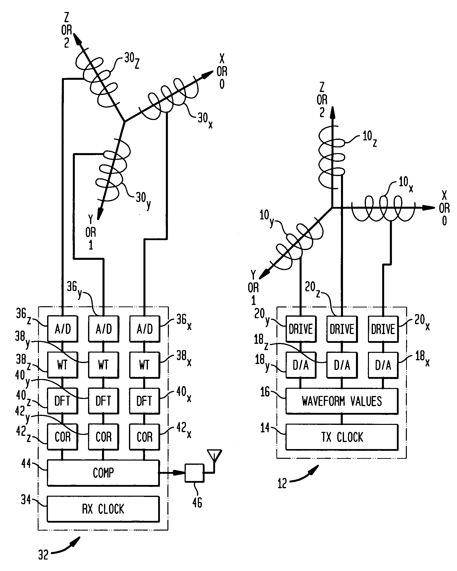
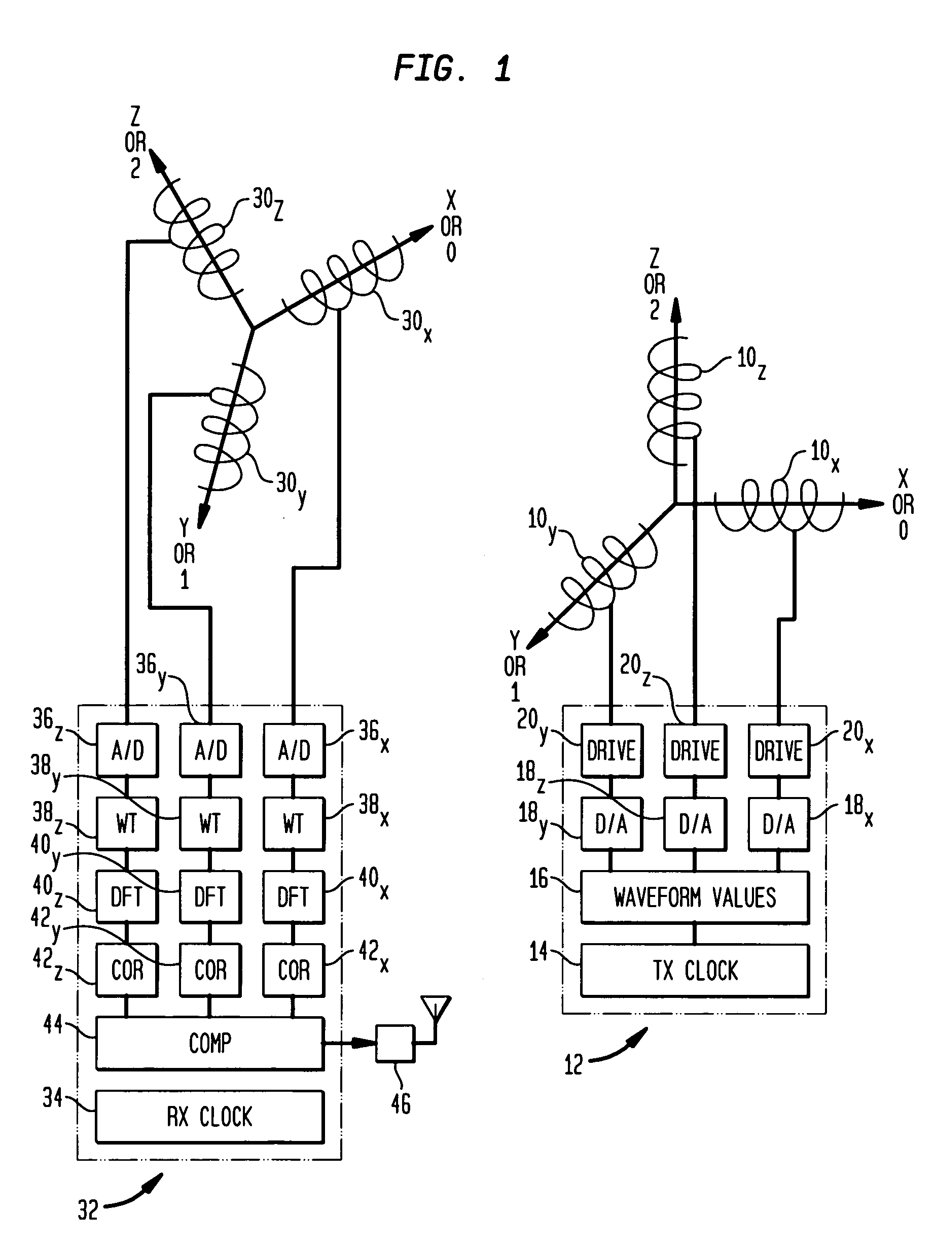
[0022]In the description below and the accompanying drawings, functional elements of the receiver are shown and described as separate circuits for ease of understanding. Likewise, functional elements of the transmitter are shown and described as separate circuits. However, this should not be taken as requiring separate physical components. For example, a programmable component such as a microprocessor or ASIC may be arranged to fulfill the roles of different circuit elements at different times, and a single component may serve as part or all of two or more of the functionally-described separate circuits.

[0023]A transmitter in accordance with one embodiment of the invention includes a set of three collocated coils 10X, 10Y and 10Z disposed along three mutually orthogonal axes, arbitrarily labeled “X,”“Y”, and “Z” (or, alternatively, 0, 1, and 2, respectively). The axes of the coils define a conventional Cartesian coordinate system or frame of reference. Although the coils are shown a...


PUM


Abstract

Plural transmitter coils of a magnetic locating system are driven with widely-separated main frequencies. One of the transmitter coils is also driven with a marker frequency close to the main frequency applied to that coil. The receiver determines a phase relationship with the transmitter based on the main and marker frequencies, so that the receiver does not suffer from phase ambiguity. The main and marker frequencies may interfere with one another, and the receiver may correct for such interference based on known characteristics of the signals at the main and marker frequencies.

Description

CROSS-REFERENCE TO RELATED APPLICATIONS[0001]The present application claims benefit of the filing date of U.S. Provisional Patent Application No. 60 / 934,356, filed Jun. 13, 2007, the disclosure of which is incorporated by reference herein.FIELD OF THE INVENTION[0002]The present invention relates to magnetic locators, commonly also referred to as magnetic tracking systems.BACKGROUND OF THE INVENTION[0003]A magnetic tracking system includes a sender or transmitter which applies magnetic fields in space, and a sensor which detects the fields. Most commonly, the transmitter includes three coils directed along three mutually orthogonal axes. Typically, these coils are co-located, i.e., wound so that their centers are at or very near to the same point in space. The sensor or receiver typically includes a similar assembly of three coils or other sensors. The position and orientation of the receiver in the frame of reference of the transmitter can be determined from the set of relationships...

Claims


Application Information

Patent Timeline
Patent Type & Authority Applications(United States)
IPC IPC(8): G01B7/00
CPCA61B19/5244A61B2019/5251G01V3/12G01R33/04A61B2019/5483A61B2090/3983A61B34/20A61B2034/2051
Inventor JONES, HERBERT R.HIGGINS, ROBERT F.HIMBERG, HENRY E.
Owner ALKEN INC DBA POLHEMUS
Why Eureka
Try Eureka