Error correction coding apparatus

a coding apparatus and error correction technology, applied in the field of error correction coding apparatus, can solve the problem that the performance of short-length lt codes is not particularly good, and achieve the effect of improving the performan

Inactive Publication Date: 2009-01-29
MITSUBISHI ELECTRIC CORP
View PDF9 Cites 23 Cited by
  • Summary
  • Abstract
  • Description
  • Claims
  • Application Information

AI Technical Summary

Benefits of technology

[0005]Because the error correction coding apparatus in accordance with the present invention forms a deterministic systematic low-density parity-check code using a pseudo circulant matrix, it can make a disappearance correction with a high degree of efficiency even if the low-density parity-check code has a short code length.

Problems solved by technology

A problem with LT codes is, however, that because a random number sequence is used in order to form an LT code, good performance is not achieved particularly for a short-length LT code.

Method used


Image

  • Error correction coding apparatus
  • Error correction coding apparatus
  • Error correction coding apparatus

Examples


embodiment 1

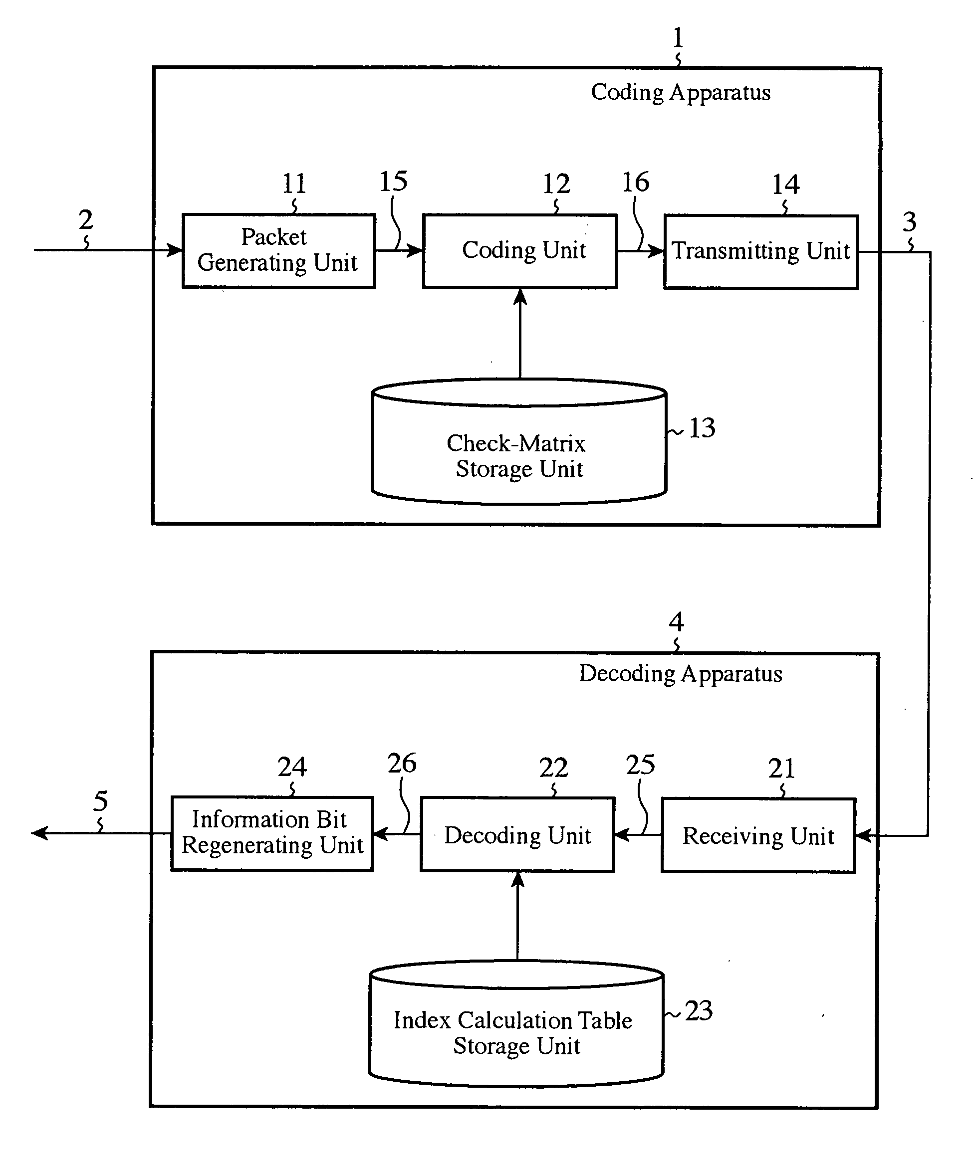
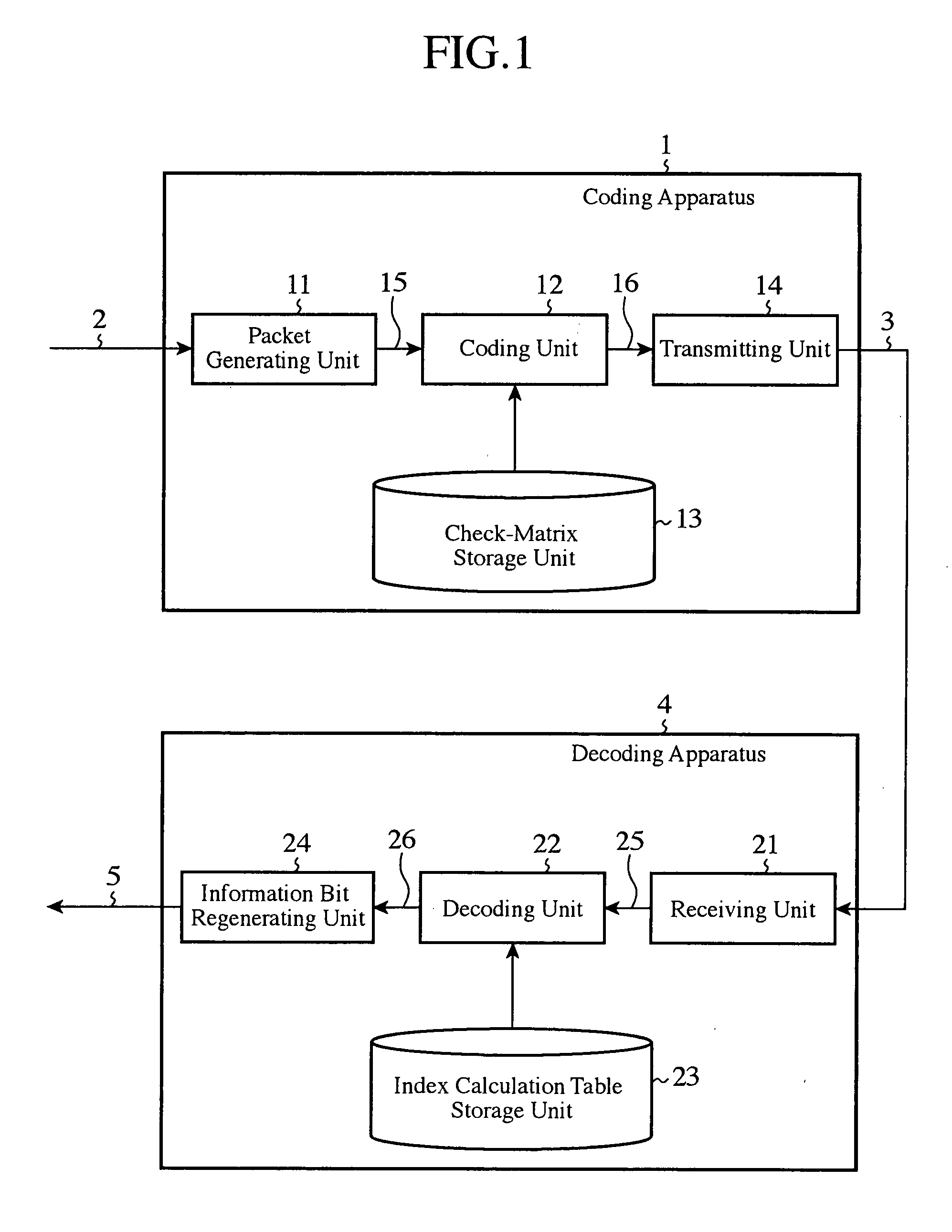
[0013]Hereafter, an error correction coding apparatus and a decoding apparatus in accordance with the present invention will be explained. In this embodiment, in order to explain concretely an error correction coding method of the present invention and a decoding method which corresponds to this encoding method, a configuration example of a system in which information is transmitted via a network is used.

[Equipment Configuration]

[0014]FIG. 1 is a block diagram showing the structures of these coding apparatus and decoding apparatus. In the figure, the coding apparatus 1 is the error correction coding apparatus in accordance with the present invention which is arranged on a side which transmits information, and which receives an information bit 2, performs error correction coding on the information bit, and transmits a signal which it has acquired as a result of the coding to the network 3. The decoding apparatus 4 is the one which corresponds to the error correction coding method in ...


PUM


Abstract

An error correction coding apparatus is disposed to generate a low-density parity-check code 16 from an input information sequence 15 by using a low-density parity-check matrix which satisfies a predetermined weight distribution, and includes a low-density parity-check matrix output means 13 for forming the above-mentioned low-density parity-check matrix by continuously arranging a number of rows in each of which the same number of cyclic-permutation matrices as the row weight are arranged, the number of rows satisfying the above-mentioned predetermined weight distribution, and then gradually increasing or decreasing the row weight, and for outputting the above-mentioned low-density parity-check matrix.

Description

FIELD OF THE INVENTION[0001]The present invention relates to an error correction coding apparatus. More particularly, it relates to a technology for forming a deterministic systematic low-density parity-check code using a pseudo circulant matrix.BACKGROUND OF THE INVENTION[0002]An LT (Luby Transfer) code is representative of prior art disappearance correction codes. Features of this code are that it assumes a communication path as a disappearance communication path, a transmitter side can arbitrarily code a packet having an information length k so that the packet has a code length n which falls within the limit n>k, and a receive side can succeed in decoding the information packet k only by successfully receiving at most (n+ε) (ε≈1.05 to 1.2×n) packets (for example, see nonpatent reference 1).[Nonpatent reference 1] Michael Luby, “LT codes”, in Proceedings of ACM Symposium on FOCS, 2002.[0003]A problem with LT codes is, however, that because a random number sequence is used in or...

Claims


Application Information

Patent Timeline
Patent Type & Authority Applications(United States)
IPC IPC(8): H03M13/11G06F11/10
CPCH03M13/1102H03M13/373H03M13/116H03M13/1148H03M13/19H04L1/00
Inventor MATSUMOTO, WATARUSAKAI, RUIYOSHIDA, HIDEO
Owner MITSUBISHI ELECTRIC CORP
Why Eureka
Try Eureka