Method and Apparatus for Scheduling Grid Jobs Using a Dynamic Grid Scheduling Policy

a grid job and dynamic scheduling technology, applied in the field of data processing system, can solve the problems of inefficiency, static scheduling policies that fail to efficiently utilize resources for applications, and the most challenging performance of resource management and scheduling

Active Publication Date: 2009-01-29
KYNDRYL INC
View PDF4 Cites 129 Cited by
  • Summary
  • Abstract
  • Description
  • Claims
  • Application Information

AI Technical Summary

Problems solved by technology

Among these services, the resource management and scheduling tends to be the most challenging to perform optimally.
Static scheduling policies can fail to efficiently utilize resources for applications and resources that fall outside the scope of the policy.
However, in this example, inefficiencies can occur when an insufficient number of nodes are available to process the next parallel job in a job queue.
The static scheduler may then fail to utilize idle nodes to execute non-parallel jobs.
Also, the static scheduler associated with the idle nodes may not have the functionality to execute non-parallel jobs.
As a result, resources that could be used to execute non-parallel jobs are left idle, and are therefore under-utilized.
For example, a static scheduler having the infrastructure for parallel processing may fail to receive non-parallel jobs for processing if the user or application submitting jobs to the static scheduler submits only parallel jobs.
The above example also illustrates that static schedulers having static scheduling policies are ineffective at scheduling jobs in a heterogeneous grid computing system having multiple application and resource types.
Because the various languages of the multiple static schedulers are not normalized into a uniform medium, problems may arise in coordinating the policies, status information, and resource availability information of each static scheduler into a comprehensive policy for managing all of the nodes in the heterogeneous environment.

Method used


Image

  • Method and Apparatus for Scheduling Grid Jobs Using a Dynamic Grid Scheduling Policy
  • Method and Apparatus for Scheduling Grid Jobs Using a Dynamic Grid Scheduling Policy
  • Method and Apparatus for Scheduling Grid Jobs Using a Dynamic Grid Scheduling Policy

Examples


Embodiment Construction

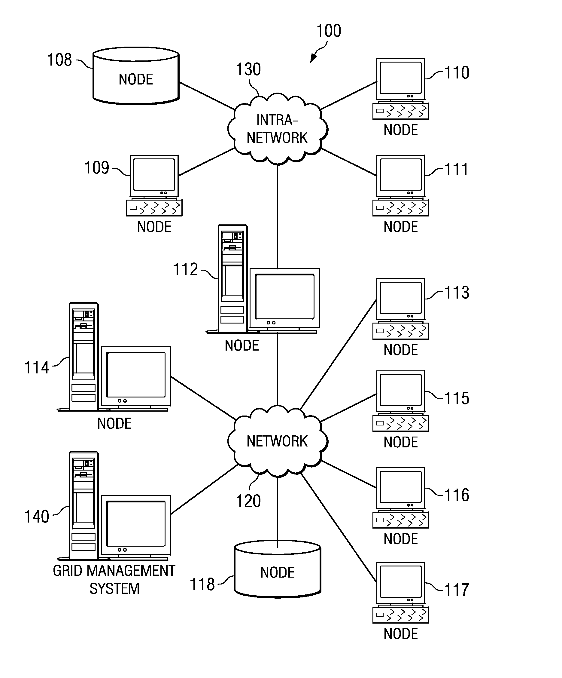
[0037]FIG. 1 is an exemplary diagram of a computing grid environment in which aspects of the present invention may be implemented. As shown in FIG. 1, computing grid 100 includes nodes 108-118 coupled together via one or more networks 120-130. The nodes may be any type of computing device that is capable of either processing grid jobs and grid data or is capable of providing such grid data to other grid nodes. For example, one of nodes 108-118 may be a server computing device, client computing device, workstation, blade, personal computer, database system, mainframe computer system, or the like.

[0038]Computing grid 100 is managed by the grid management system 140. Grid management system 140 communicates with nodes 108-118 to obtain information about each of the nodes in nodes 108-118 and to submit grid jobs and grid data to nodes 108-118 for processing. Grid management system 140 provides the necessary functionality for determining which nodes in nodes 108-118 in the computing grid ...


PUM


Abstract

The illustrative embodiments described herein provide a computer-implemented method, apparatus, and computer program product for scheduling grid jobs. In one embodiment, a process identifies information describing available resources on a set of nodes on a heterogeneous grid computing system to form resource availability information. The process identifies a set of static scheduling policies for a set of static schedulers that manage the set of nodes. The process also identifies a static scheduling status for a portion of the set of static schedulers. The process creates a dynamic grid scheduling policy using the resource availability information, the set of static scheduling policies, and the static scheduling status. The process also schedules a set of grid jobs for execution by the available resources using the dynamic grid scheduling policy.

Description

BACKGROUND OF THE INVENTION[0001]1. Field of the Invention[0002]The present invention relates generally to a data processing system and in particular to a method and system for scheduling grid jobs. More particularly, the present invention is directed to a computer-implemented method, apparatus, and computer-usable program code for scheduling grid jobs using a dynamic grid scheduling policy.[0003]2. Description of the Related Art[0004]In the 1990's, computer scientists began exploring the design and development of a computer infrastructure, referred to as the computation grid, whose design was based on the electrical power grids that had been known to date. Grid computing was initially designed for use with large-scale, resource intensive scientific applications, such as the Search for Extraterrestrial Intelligence (SETI) program's computing grid. This type of application requires more resources than a small number of computing devices can provide in a single administrative domain. ...

Claims


Application Information

Patent Timeline
Patent Type & Authority Applications(United States)
IPC IPC(8): G06F9/46
CPCG06F9/5072G06F9/4881
Inventor MAUSOLF, JEFFRY RICHARDSTEPHENS, KIMBERLY ANN
Owner KYNDRYL INC
Why Eureka
Try Eureka