Lath support system

a technology of lath support and support rod, which is applied in the direction of walls, covering/linings, constructions, etc., can solve the problems of cracking of stone, plaster, or stucco, visible, unstable, and unattractive, so as to save labor costs, save installation time, and increase the coverage

Inactive Publication Date: 2009-02-05
SPIDERLATH
View PDF48 Cites 25 Cited by
  • Summary
  • Abstract
  • Description
  • Claims
  • Application Information

AI Technical Summary

Benefits of technology

[0043]Non-metallic mesh has advantages with respect to prior art metal systems, which had to be hung in a correct orientation to function properly. The mesh of the current invention can be hung in any orientation, which makes installation at least 40% faster.
[0044]A non-metallic mesh provides greater coverage per roll as compared to metal lath. The rolls of non-metallic mesh are 4 feet wide, as opposed to the 27 in for metal lath. A mason can carry a roll of non-metallic lath up scaffolding and attach the non-metallic lath at the top of the substrate and let the rest of the roll of lath fall to the ground. The suspended mesh may then be fastened to the substrate. In contrast, metal lath is cumbersome, heavy, and dangerous to transport to great heights.
[0045]The installation of a non-metallic lath saves on installation time, thus saving on labor costs. The labor savings is at least 50% over the metal for example a manufactured stone installer, can save over 50% in labor in residential projects, and in some commercial projects that have long straight runs, 80%. The minimum savings on installation is 50%.
[0046]The scratch coat is easy to apply on a fiberglass mesh lath material, wherein the

Problems solved by technology

If the metallic lath is weakened by corrosion, cracks tend to result in the cementations material.
In some cases, crack propagation may result in cracking of the stone, plaster, or stucco, which may be visible, unattractive, and unstable.
The corrosive effects resulted from moisture and alkalinity due to the lime content in cement based mortar.
However, galvanized metal lath still has a tendency to rust and deteriorate, thus providing a substrate that is prone to fail.
Fiberglass mesh, while not usually subject to corrosion, can be affected by the corrosive nature of cementitious material.
If the water proo

Method used


Image

  • Lath support system
  • Lath support system
  • Lath support system

Examples


Embodiment Construction

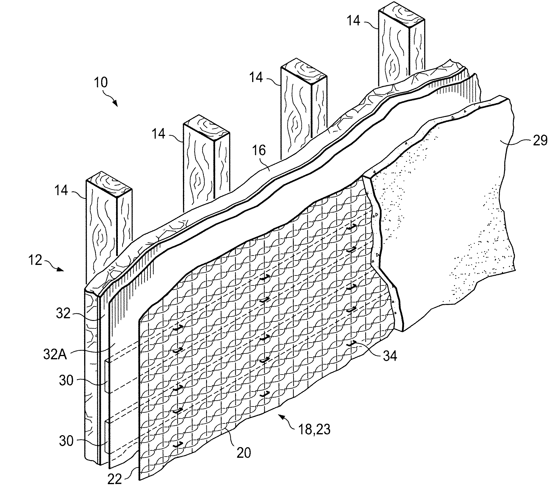
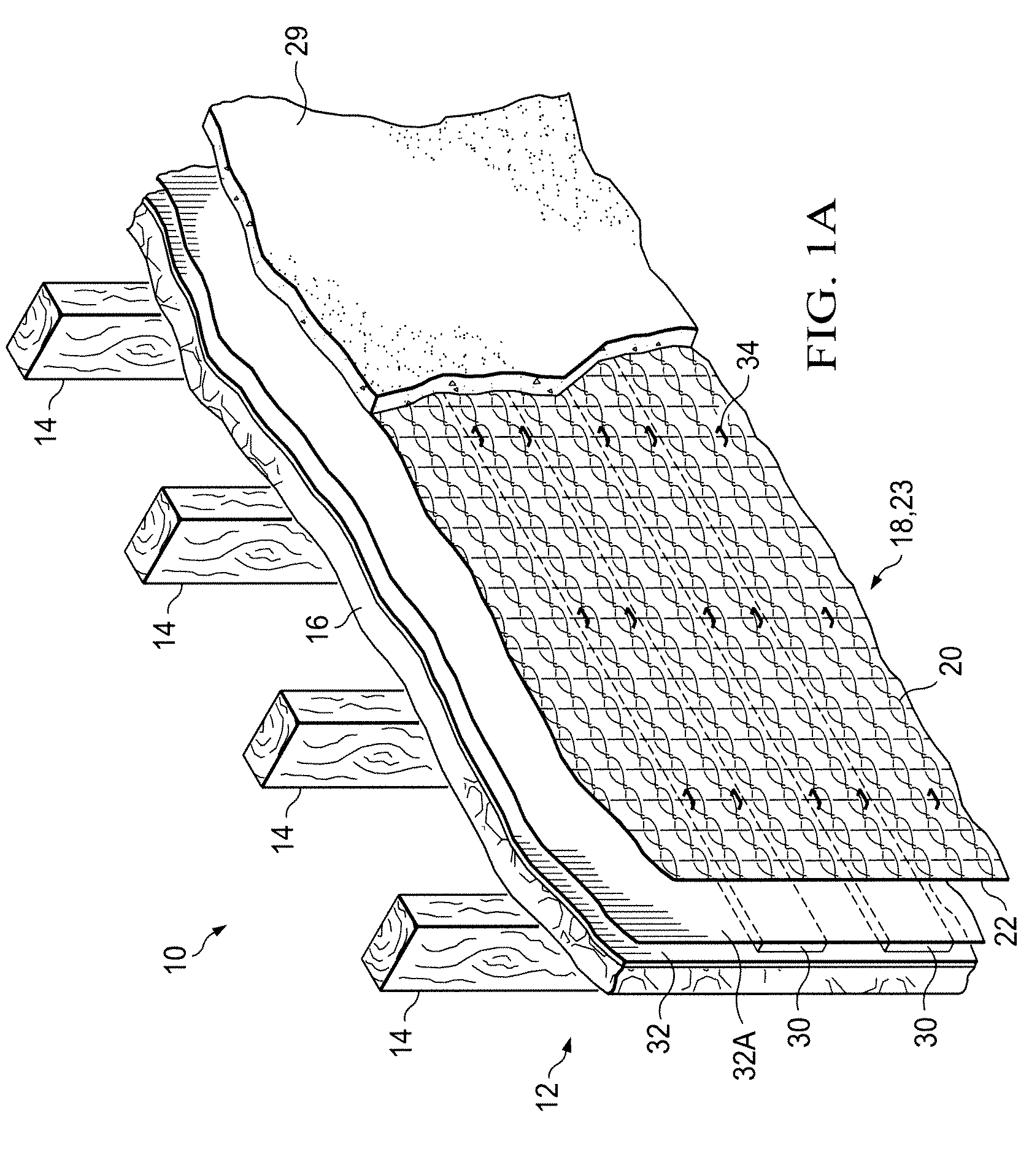
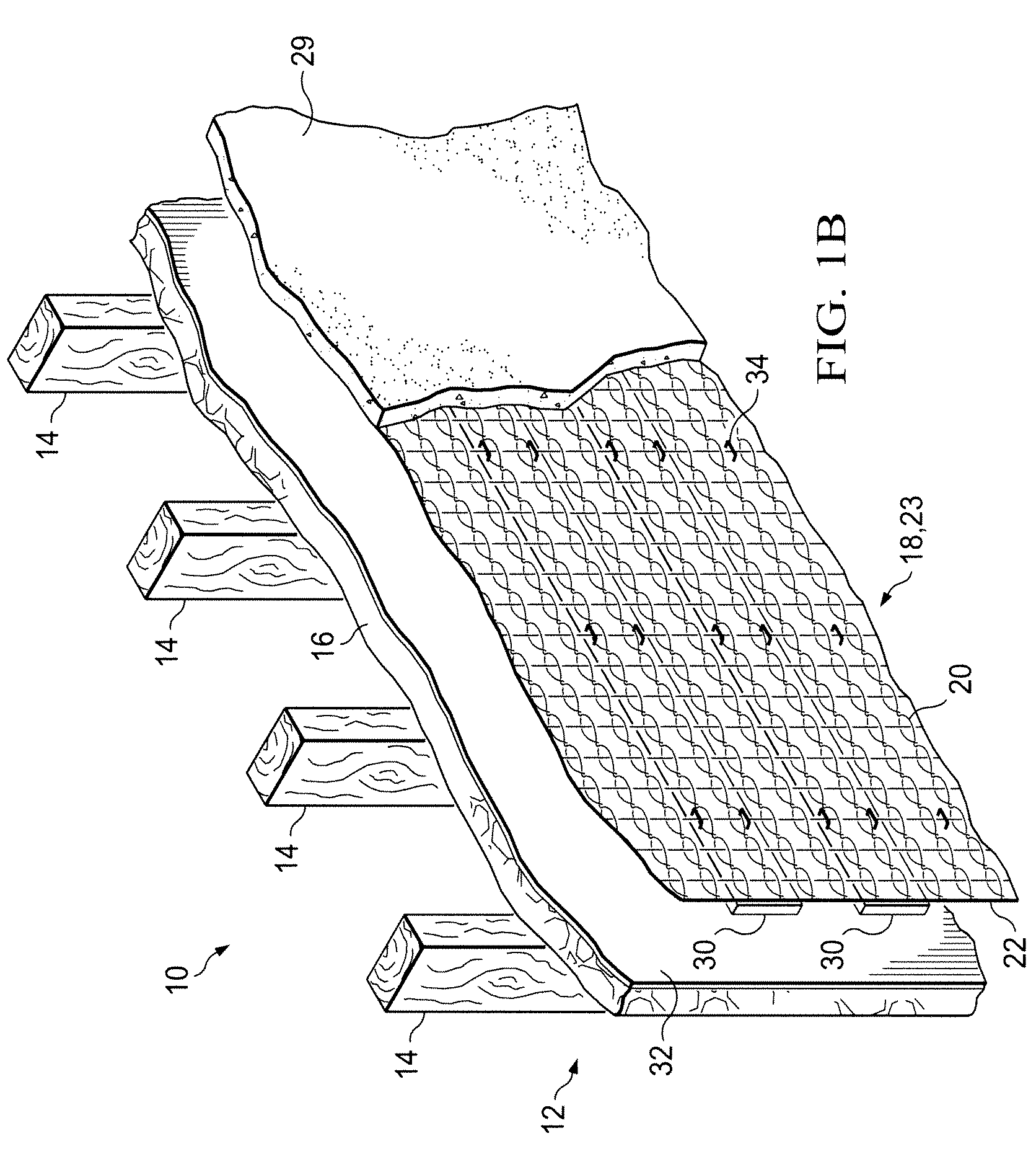
[0062]Referring now to FIG. 1B, the structural reinforcement system 10 of the invention is shown. Structural reinforcement system 10 is affixed to support structure 12. Support structure 12 typically is made up of a plurality of studs 14 which may be covered with sheathing 16. An example of sheathing 16 is oriental strand board (OSB). A lath 18 is located adjacent to support structure 12. Lath 18 has a front surface 20 and a rear surface 22.

[0063]In one embodiment (FIGS. 1A-6) lath 18 is a mesh structure 23. Mesh structure 23 may be a metal lath or a non-metallic lath. In the embodiment wherein lath 18 is a non-metallic lath, mesh structure 23 includes a first group of a plurality of strands 24 (best shown in FIGS. 3-6) that are generally parallel to one another, e.g., horizontal strands. Mesh structure 23 further includes a second group of strands 26 that are generally parallel to one another and transverse to the first group of plurality of strands 24, e.g., vertical strands. Firs...


PUM


Abstract

A structural reinforcement system that utilizes a lath for receiving cementitious material. Lath is affixed to support structure such as sheathing supported by studs as may commonly be found in building construction. Strip members are affixed to the lath and function as fastener guides. Fasteners penetrate the strips for affixing lath and strips to the support structure. The strips are made of a compressible material that protects the lath from damage due to impacts associated with installing the fasteners and forms a gasket-like seal around the fasteners. Strips may be used as drainage guides for directing water that may flow behind the lath. The width of the strips creates spacing between the lath and the support structure, which allows for controlling of a thickness of a base layer of cementitious material by selecting a desired width. In another embodiment, entangled filaments are used as lath material for receiving cementitious material.

Description

CROSS REFERENCE TO RELATED APPLICATIONS[0001]This application claims priority of U.S. Provisional Patent Application No. 60 / 937,623, entitled “NON-METALLIC MESH SUPPORT SUBSTRATE,” filed Jun. 28, 2007, the contents of which are hereby incorporated by reference.FIELD OF THE INVENTION[0002]The present invention is directed to improvements in lath support systems for use in a variety of applications. The present invention is also directed to a method of applying lath and strip members as part of a structural reinforcement system.BACKGROUND OF THE INVENTION[0003]Plastering is one of the oldest crafts in the building trades. Plastering remains popular due to the durability and relatively low cost of materials. Plasterers apply plaster to interior walls and ceilings to form fire-resistant and relatively soundproof surfaces. A plaster veneer may also be applied over drywall to create smooth or textured abrasion-resistant finishes. In addition, prefabricated exterior insulation systems may ...

Claims


Application Information

Patent Timeline
IPC IPC(8): E04F13/04
CPCE04F13/047E04F13/04E04B2/845E04F13/045E04F13/0803
Inventor HUNT-HANSEN, MARY JANELOVE, ROBERT WAYNEFOSTER, WILLIAM CLYDEJOHNSON, SR., WILLIAM L.
Owner SPIDERLATH
Why Eureka
Try Eureka