Angular velocity sensor interface circuit and angular velocity detection apparatus

a sensor interface and angular velocity technology, applied in the direction of acceleration measurement using interia force, turn-sensitive devices, instruments, etc., can solve the problem that the camera shake compensation cannot be performed simultaneously, and achieve the effect of reducing the activation tim

Inactive Publication Date: 2009-02-05
MURATA MFG CO LTD
View PDF6 Cites 16 Cited by
  • Summary
  • Abstract
  • Description
  • Claims
  • Application Information

AI Technical Summary

Benefits of technology

[0012]To overcome the problems described above, preferred embodiments of the present invention provide an angular velocity sensor interface circuit and an angular velocity detection apparatus which have reduced activation times, that is, a time after power on and before a voltage generated in accordance with an angular velocity is properly output.

Problems solved by technology

Accordingly, even if the angular velocity detection apparatus is provided to compensate for camera shake, for example, the camera shake compensation cannot be performed simultaneously upon power-on of a camera.

Method used


Image

  • Angular velocity sensor interface circuit and angular velocity detection apparatus
  • Angular velocity sensor interface circuit and angular velocity detection apparatus
  • Angular velocity sensor interface circuit and angular velocity detection apparatus

Examples


first preferred embodiment

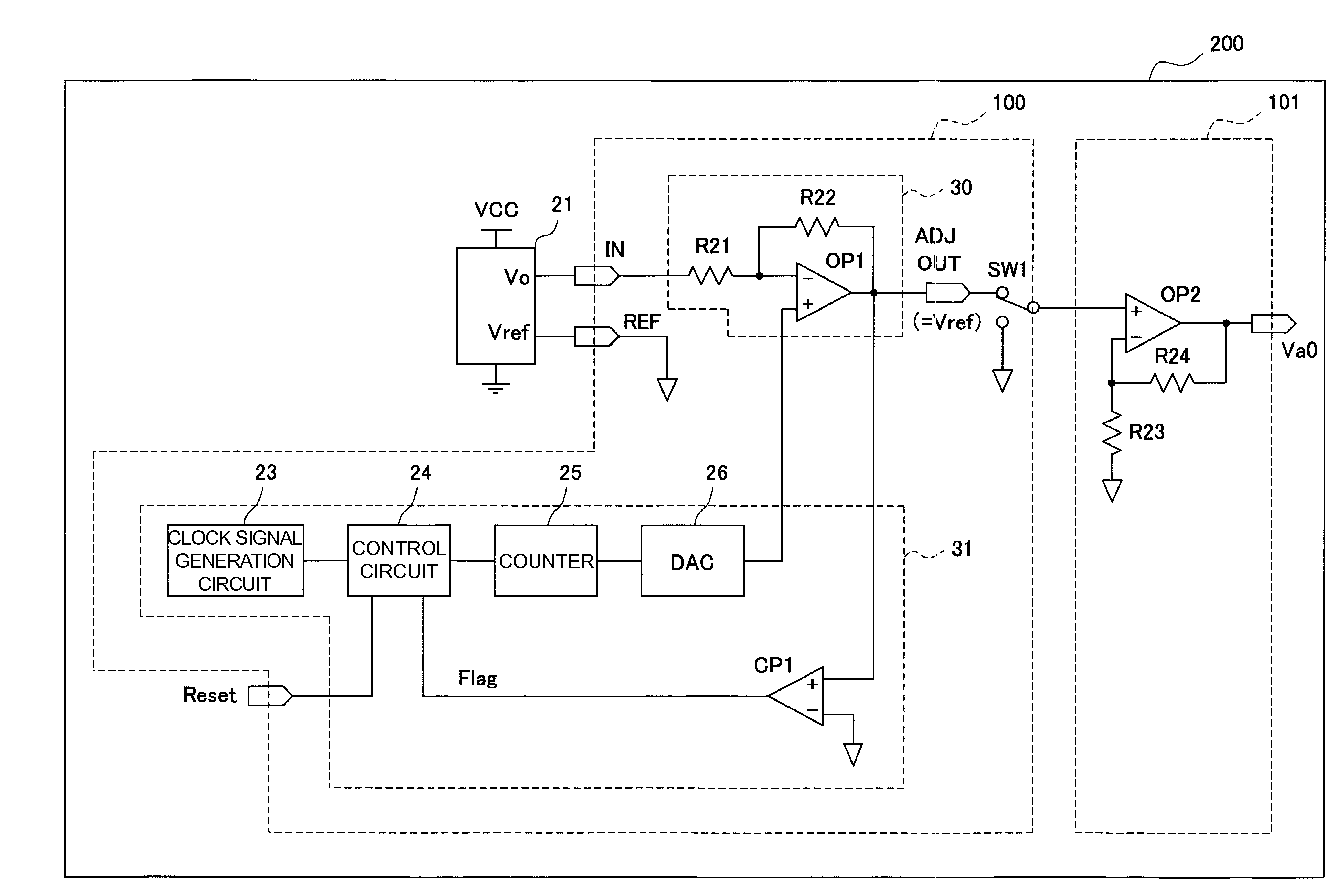
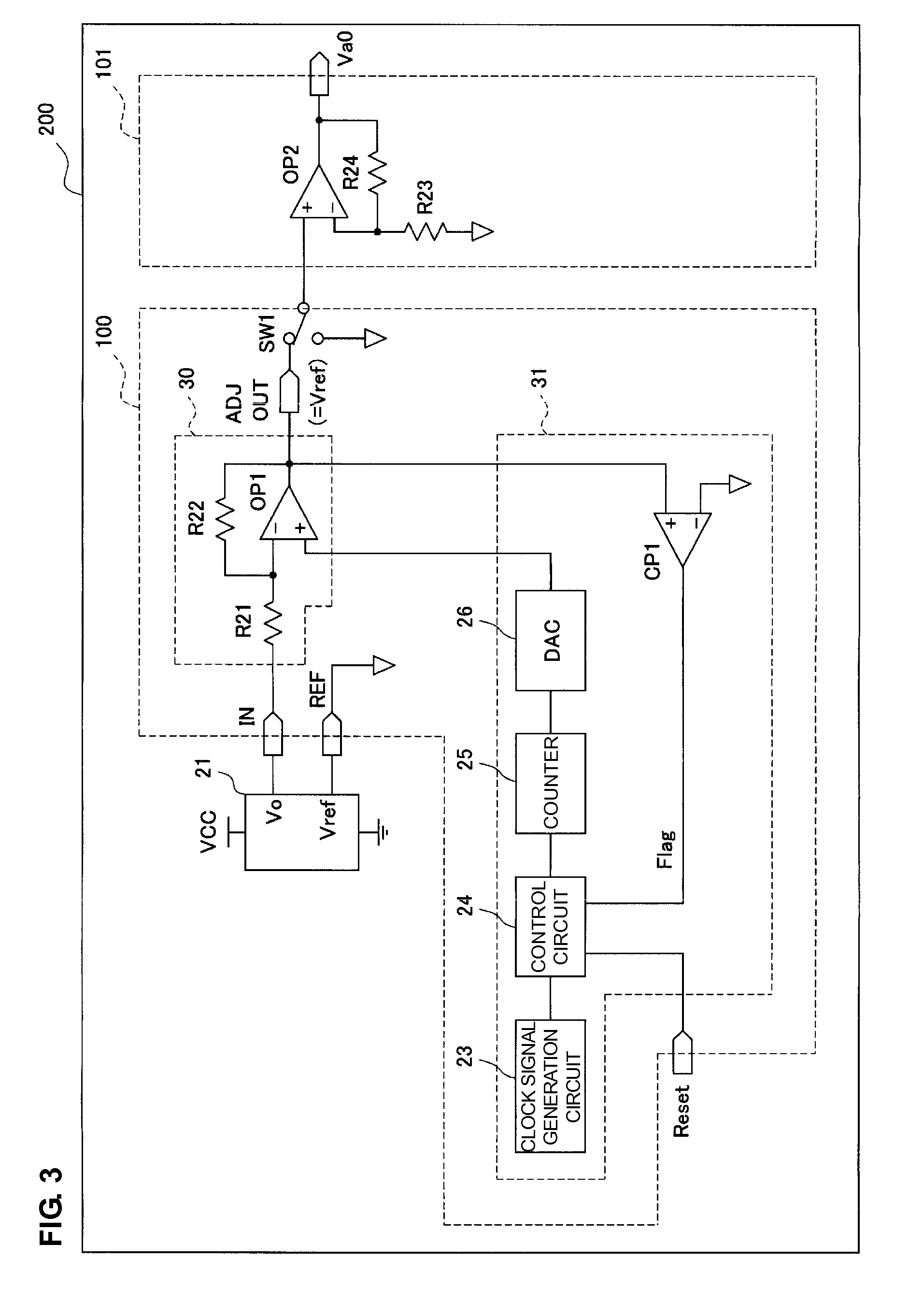
[0036]FIG. 3 is a diagram illustrating a configuration of an angular velocity sensor interface circuit and an angular velocity detection apparatus according to a first preferred embodiment of the present invention.

[0037]In FIG. 3, an angular velocity detection apparatus 200 includes an angular velocity sensor 21, an angular velocity sensor interface circuit 100, and an angular velocity signal processing circuit 101.

[0038]The angular velocity sensor 21 includes a piezoelectric vibrator and a circuit which drives the piezoelectric vibrator and which detects a voltage generated by vibration of the piezoelectric vibrator. The angular velocity sensor 21 outputs a reference voltage Vref and an angular velocity detection signal Vo which is a voltage signal generated in accordance with an applied angular velocity.

[0039]The angular velocity sensor interface circuit 100 performs direct-current amplifying processing of the angular velocity detection signal Vo output from the angular velocity s...

second preferred embodiment

[0053]An angular velocity sensor interface circuit and an angular velocity detection apparatus according to a second preferred embodiment of the present invention will now be described with reference to FIGS. 6 to 8.

[0054]FIG. 6 is a diagram illustrating a configuration of the angular velocity sensor interface circuit and the angular velocity detection apparatus according to the second preferred embodiment of the present invention. The configuration of the angular velocity sensor interface circuit and the angular velocity detection apparatus shown in FIG. 6 is different from the configuration of the angular velocity sensor interface circuit and the angular velocity detection apparatus shown in FIG. 3 in that a high-pass filter 22 including a capacitor C21 connected to an output terminal of the angular velocity detection signal amplifier circuit 30 in series and a shunt resistor R25 connected between the capacitor C21 and an reference voltage line is provided in an input section of t...

third preferred embodiment

[0065]An angular velocity sensor interface circuit and an angular velocity detection apparatus according to a third preferred embodiment of the present invention will now be described with reference to FIG. 9.

[0066]The configuration of the angular velocity sensor interface circuit and the angular velocity detection apparatus shown in FIG. 9 is different from the configuration of the angular velocity sensor interface circuit and the angular velocity detection apparatus shown in FIG. 6 in that a high-pass filter 22 does not include a discharge switch circuit SW2. As shown in FIG. 9, even when the switch SW2 which causes a short circuit at both terminals of a capacitor C21 is not arranged in the high-pass filter 22, since a switch SW1 selects a reference voltage Vref side in an offset control period, a reference voltage Vref is supplied to the input switch circuit SW1 side of the capacitor C21. Furthermore, the reference voltage Vref is also supplied through a resistor R25 to an operat...


PUM


Abstract

An angular velocity detection apparatus includes an angular velocity detection signal amplifier circuit which amplifies an angular velocity detection signal Vo output from an angular velocity sensor, and an offset control circuit which controls an offset so as to be a reference voltage which is output when a value of an angular velocity is 0. The angular velocity detection apparatus further includes an input switch circuit which selects the reference voltage and a discharge switch circuit which short-circuits a capacitor included in a high-pass filter in an offset control period.

Description

BACKGROUND OF THE INVENTION[0001]1. Field of the Invention[0002]The present invention relates to an angular velocity sensor interface circuit and an angular velocity detection apparatus used to compensate for camera shake.[0003]2. Description of the Related Art[0004]In general, a digital still camera and a digital video camera include angular velocity sensors to detect and compensate for camera shake.[0005]Such an angular velocity sensor used to compensate for camera shake includes a piezoelectric vibrator. A voltage is generated by vibration of the piezoelectric vibrator caused by a Coriolis force and outputs a voltage signal generated in accordance with an angular velocity. Note that the voltage signal output from the angular velocity sensor is amplified and converted into a voltage signal generated in accordance with an angular velocity in a control operation corresponding to an angular velocity, such as camera shake compensation, using an output signal of the angular velocity se...

Claims


Application Information

Patent Timeline
Patent Type & Authority Applications(United States)
IPC IPC(8): G01C19/56
CPCG01C25/00G01C19/56G01C25/005G01C19/00
Inventor SUGIBAYASHI, HIDEAKI
Owner MURATA MFG CO LTD
Why Eureka
Try Eureka