Marker detection apparatus and marker detection method

a detection apparatus and marker technology, applied in the direction of vibration measurement in solids, instruments, specific gravity measurement, etc., can solve the problems that the flow cytometer cannot detect the small markers, and the above flow cytometer has limitations in detecting small markers

Inactive Publication Date: 2009-02-05
SONY CORP
View PDF3 Cites 10 Cited by
  • Summary
  • Abstract
  • Description
  • Claims
  • Application Information

AI Technical Summary

Benefits of technology

[0012]In another aspect of the present invention, a marker detection apparatus detects a marker attached to a target sample from samples flowing in a sample flow, including: an elastic wave applying section that applies an elastic wave to a path of the sample flow; and a detection section that detects, when the target sample labeled by the marker that is a particle made from a piezoelectric or electrostrictive substance of a unique vibration frequency flows in the sample flow, a q

Problems solved by technology

However, the above flow cytometer has limitation in detecting the small markers, which is determined by the wavelength of t

Method used


Image

  • Marker detection apparatus and marker detection method
  • Marker detection apparatus and marker detection method
  • Marker detection apparatus and marker detection method

Examples


Embodiment Construction

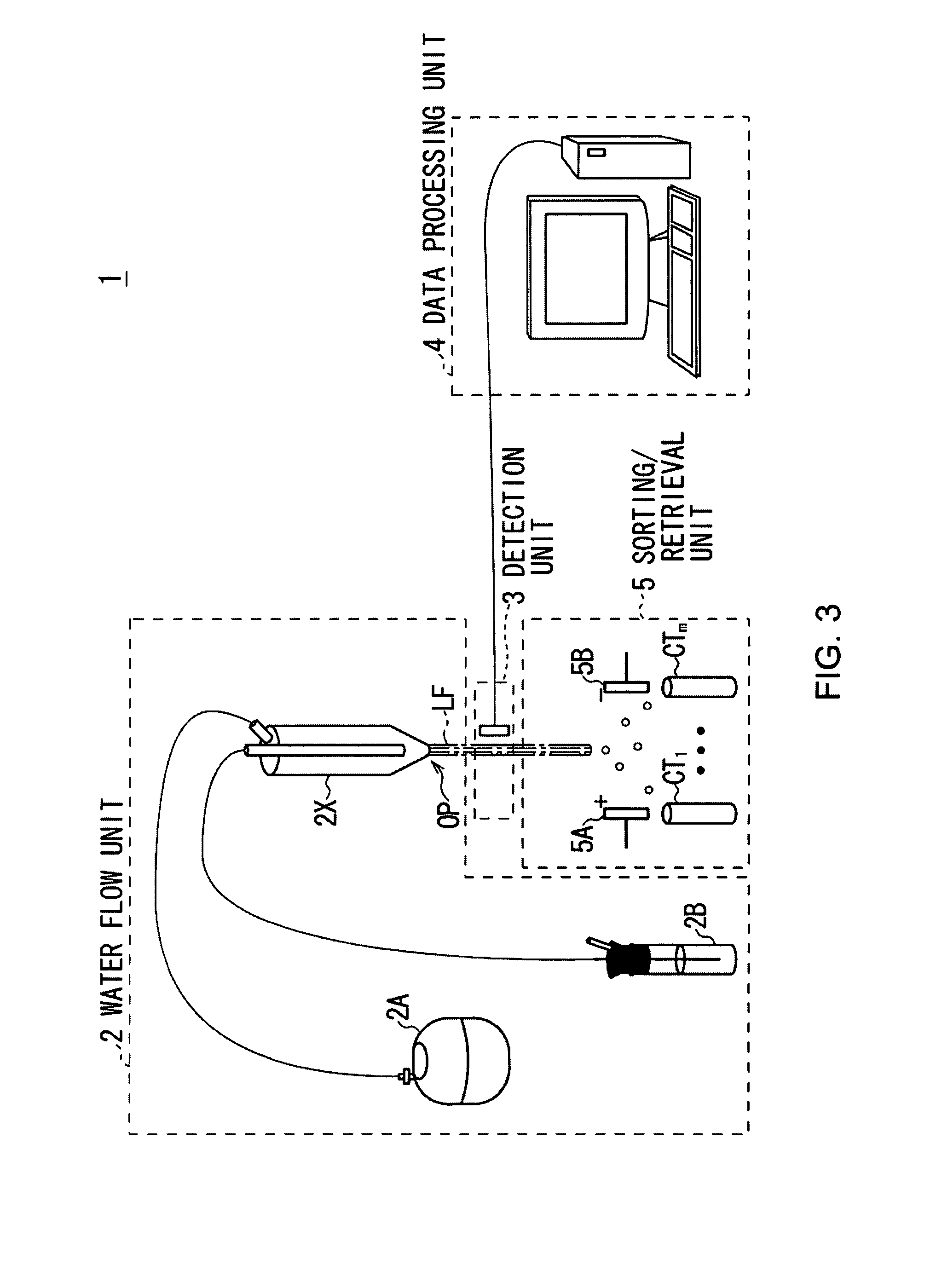
[0043]An embodiment of the present invention will be described in detail with reference to the accompanying drawings.

(1) Electric Field

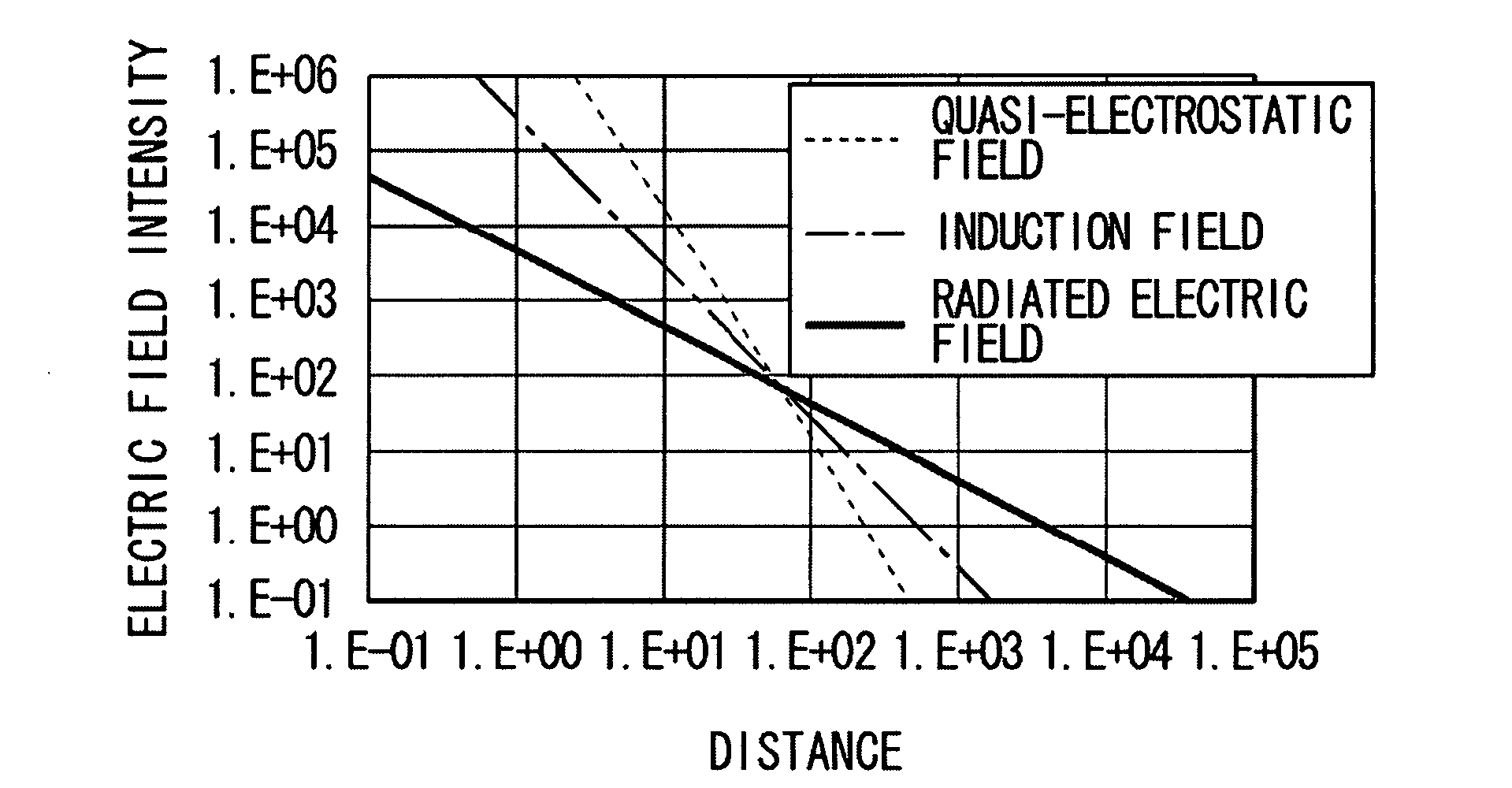
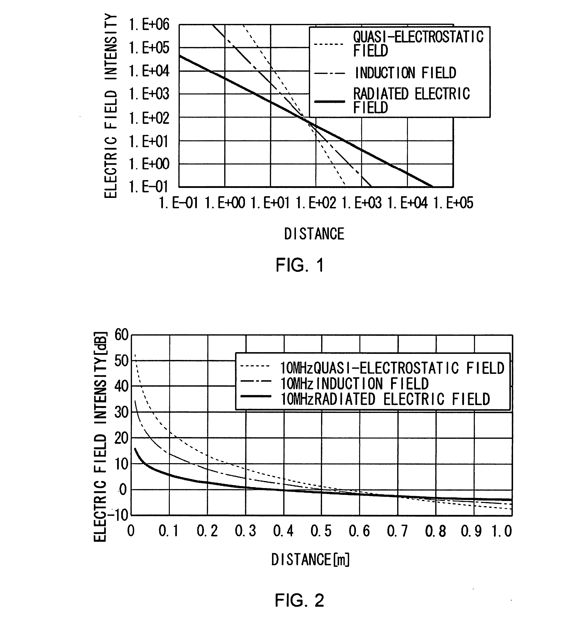
[0044]In this embodiment, a quasi-electrostatic field is used to detect a target sample labeled or marked by a marker. Various aspects of the electric field will be described, followed by description of the present embodiment for identifying the samples.

(1-1) Classification of the Electric Field

[0045]According to the Maxwell equations, an electric field intensity E at a position P is represented as follows:

Er=Qlcosθ2πɛr3(1+jkr)exp(-jkr)Eθ=Qlsinθ4πɛr3(1+jkr+(jkr)2)exp(-jkr)(1)

wherein “r” is a distance from an infinitesimal dipole or an electric field source to the position P. In this manner, the electric field intensity E is represented as a polar coordinate (r, θ, δ). By the way, in the above equation (1), “Q” means an electric charge C, “l” represents a distance between the electric charges (according to the definition of the infinitesimal dipole, “...


PUM


Abstract

A marker detection apparatus detects a marker attached to a target sample from samples flowing in a sample flow, including: an electric field formation section that forms a quasi-electrostatic field in a path of the sample flow; and a detection section that detects, when the target sample labeled by the marker that is a particle made from a piezoelectric or electrostrictive substance of a unique vibration frequency gets into the quasi-electrostatic field, the vibration of the particle.

Description

CROSS REFERENCES TO RELATED APPLICATIONS[0001]The present invention contains subject matter related to Japanese Patent Application JP2006-287898 filed in the Japanese Patent Office on Oct. 23, 2006, the entire contents of which being incorporated herein by reference.BACKGROUND OF THE INVENTION[0002]1. Field of the Invention[0003]The present invention relates to a marker detection apparatus and marker detection method, and is preferably applied to a flow cytometry technique, for example.[0004]2. Description of the Related Art[0005]There are methods to retrieve a target living cell from various cells, and one of them is flow cytometry. Flow cytometry uses a flow or stream: the target samples, labeled by fluorescent substances or a marker under a certain condition, are put into the flow one by one. In addition, a laser beam is directed onto the droplets of the flow at a right angle.[0006]There is a flow cytometer that has an optical component to sort the scattered or fluorescent light ...

Claims


Application Information

Patent Timeline
IPC IPC(8): G01H1/00
CPCG01N15/1031G01N29/036G01N29/222G01N33/54313G01N2291/0427G01N2291/0256G01N2291/0423G01N2291/0426G01N2291/0255
Inventor TAKIGUCHI, KIYOAKI
Owner SONY CORP
Why Eureka
Try Eureka