

Motor shaft for micromotor, and micromotor
a technology of motor shafts and micromotors, which is applied in the direction of toothed gearings, dynamo-electric machines, gearings, etc., can solve the problems of inability to achieve sufficient high reduction ratio, inability to increase the number of gears of the speed-reduction gear mechanism without limitation, and inability to reduce the diameter of the pinion without limitation. , to achieve the effect of high reduction ratio, low failure rate and high coaxiality
Inactive Publication Date: 2009-02-05
NAMIKI PRECISION JEWEL CO LTD
View PDF12 Cites 16 Cited by
- Summary
- Abstract
- Description
- Claims
- Application Information
AI Technical Summary
Benefits of technology
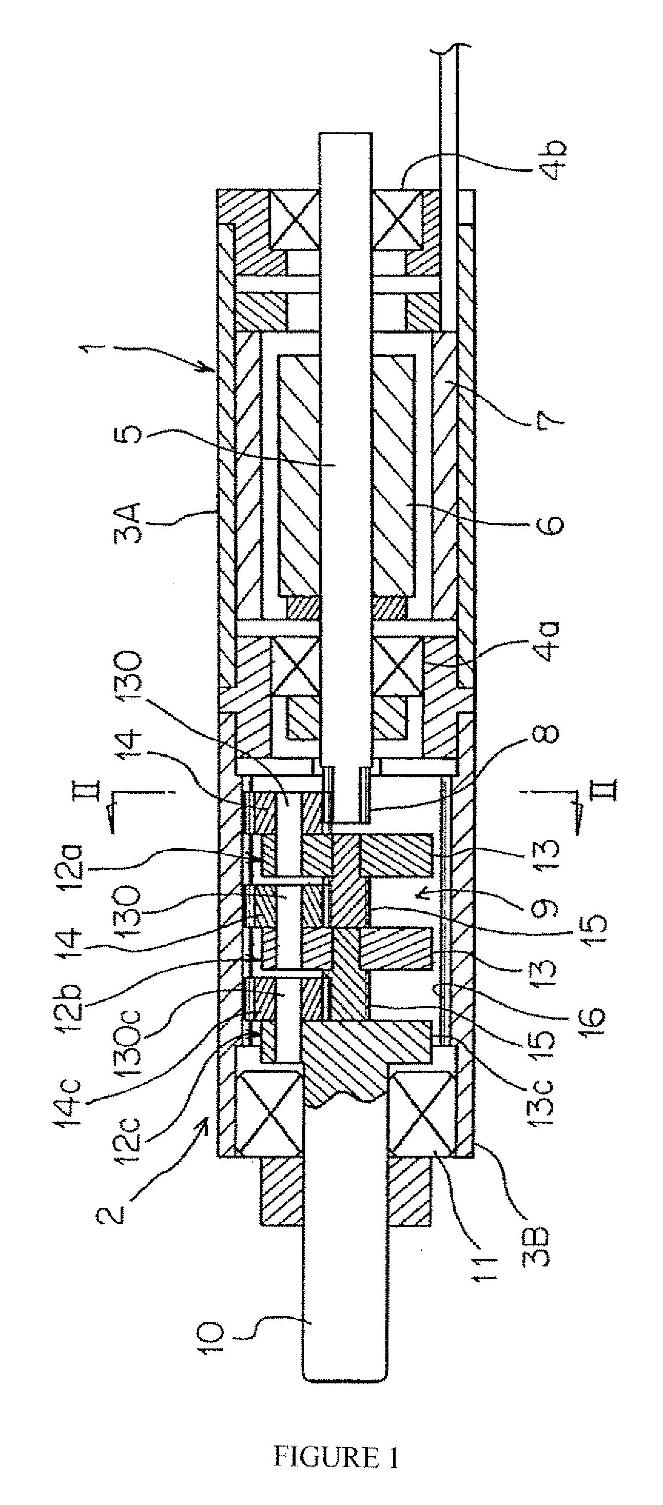
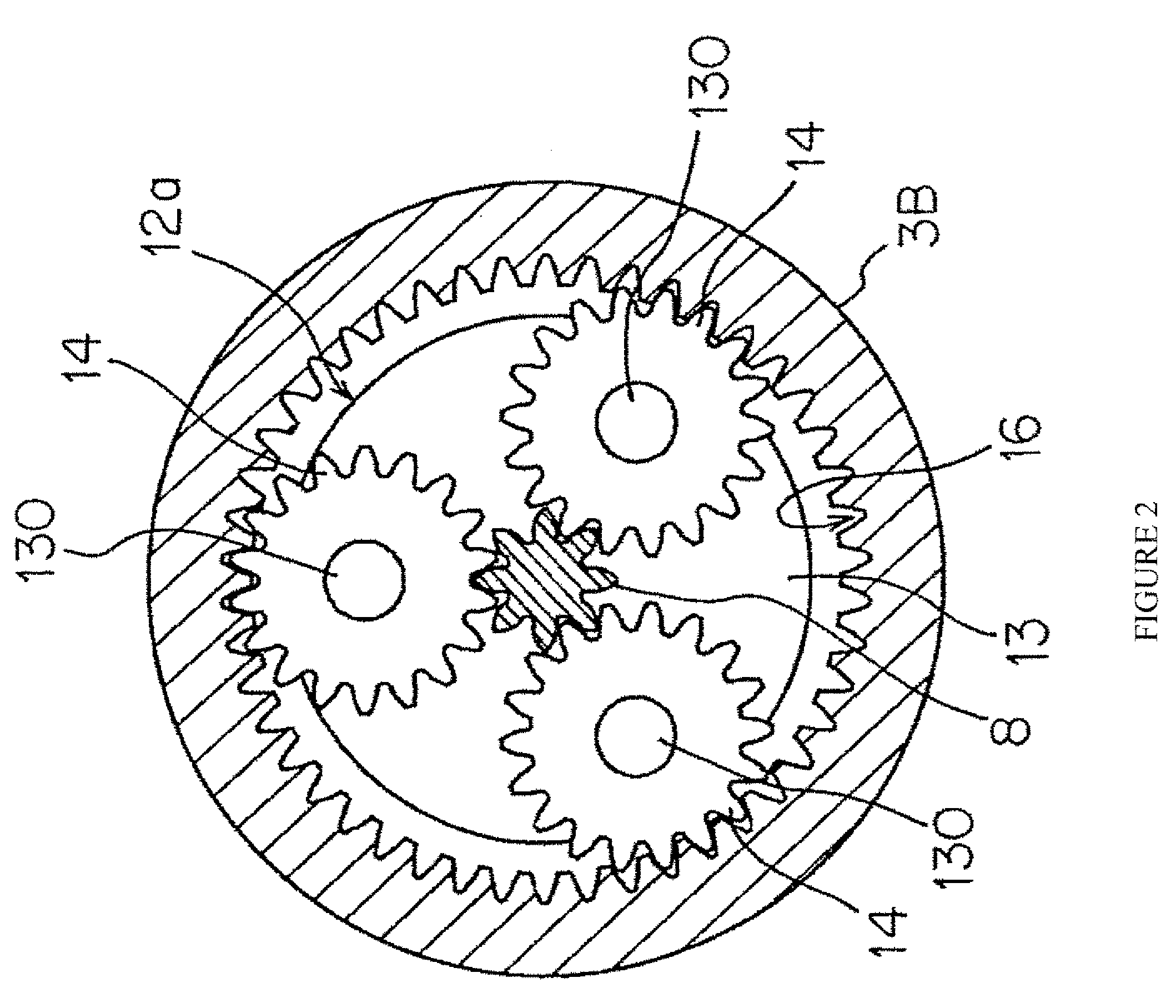
[0021]In a motor shaft for a micromotor, a micromotor provided with the motor shaft, and a micro geared motor provided with the motor shaft, since a pinion having a sufficiently small diameter can be implemented, a high reduction ratio can be obtained by a speed-reduction gear mechanism. In addition, since the pinion is integrally formed on the motor shaft, high coaxiality between the motor shaft and the pinion can be acquired. Accordingly, a motor having a low failure rate, a long lifecycle, and a low noise can be implemented. Moreover, the problem of pinion slip can be prevented. In addition, since a jointing process for the pinion by adhering, pressing, or the like is unnecessary, the number of production processes or production cost can be reduced.
Problems solved by technology
However, since the speed-reduction gear head unit has a limitation in size (diameter), the teeth number of the gear of the speed-reduction gear mechanism portion cannot be increased without limitation.
In addition, in the micro geared motor having the aforementioned construction, the diameter of the pinion cannot be decreased without limitation.
Therefore, the conventional micro geared motor has a problem in that a sufficiently high reduction ratio cannot be obtained.
In addition, the conventional micromotor in which the pinion is jointed to the motor shaft by using an adhering method or a pressing method has the following problems in the jointing structure.
(a) Since a process for adhering or pressing the motor shaft into the micro-sized pinion is needed, production cost is increased.
In addition, since a jointed portion therebetween is loosened during repetitive operations, a problem of pinion slip or the like may occur.
Method used
View moreImage
Smart ImageViewing Examples

Examples
convention example
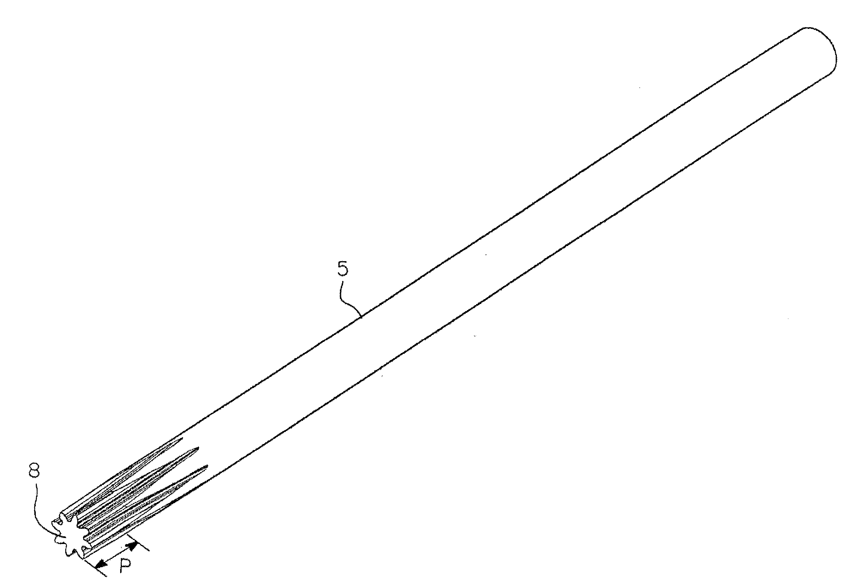
[0047]Teeth Number Z1 of Pinion (=Sun Gear): 14
[0048]Teeth Number Z2 of Planetary Gear: 15
[0049]Teeth Number Z3 of Inner Gear: 46
[0050]Reduction Ratio=(Z3 / Z1+1)≈4.286 (4.286:1)
Login to View More PUM
 Abstract
[Problems] A motor shaft for a micromotor where a high reduction ratio can be obtained by a speed-reduction gear mechanism and where high coaxiality between the motor shaft and a pinion can be achieved.[Means for Solving problems] The invention is based on the fact that, because a micromotor has a very small motor torque, even a pinion having a diameter smaller than that of a shaft has sufficient strength for the motor torque. Based on this, the motor shaft of the invention has a pinion integrally formed on the front end side of the shaft and the pinion has an outer diameter equal to or less than that of the shaft. Because the pinion can be sufficiently reduced in diameter, a high reduction ratio can be obtained by a speed-reduction gear mechanism. In addition, since the pinion can be integrally formed on the motor shaft, high coaxiality between the shaft and the pinion can be achieved.
Description
TECHNICAL FIELD[0001]The present invention relates a motor shaft for a micromotor used as a driving source of various small-sized apparatuses, a micromotor provided with the motor shaft, and a micro geared motor.BACKGROUND ART[0002]Conventionally, a micrometer having an outer diameter of about several millimeters is used as a driving source of a vibrator in a silent mode, which is built in a mobile phone. Such a micrometer is expected to be widely used as a driving source of various advanced apparatuses such as medical instruments (for example, a lens driving mechanism of a front-end portion of an endoscope and a driving mechanism for a fetal diagnosis treatment apparatus).[0003]In general, in case of a micrometer used for a small-sized apparatus such as a medical instrument, a micro geared motor provided with a gear head having a speed-reduction gear mechanism is assembled into the apparatus (for example, refer to Patent Reference 1).Patent Reference 1 Japanese Patent Application L...
Claims
Login to View More Application Information
Patent Timeline
 Patent Type & AuthorityApplications(United States)
IPC IPC(8): H02K7/116
CPCF16H1/46F16H57/08Y10T74/19684H02K7/116H02K7/003H02K7/00
InventorSHIMIZU, YUKIHARUFUKUSHIMA, ERIWATANABE, DAICHI
OwnerNAMIKI PRECISION JEWEL CO LTD