Position adjustable awning equipped with solar cell plates thereon

a solar cell and awning technology, applied in the field of awnings, can solve the problems of module limitation, roof, module plate size, module weight, etc., and achieve the effect of limiting the efficiency of sunlight utilization, maximizing sun light efficiency, and blocking the heat of the sun

Inactive Publication Date: 2009-02-05
OAK EUGENE
View PDF4 Cites 53 Cited by
  • Summary
  • Abstract
  • Description
  • Claims
  • Application Information

AI Technical Summary

Benefits of technology

[0006]Since the development of photovoltaic solar cell, many kinds of solar cells and methods of assembling the cells into a module, including the methods of assembling the solar cells for mounting on a house roof, have been introduced. Those methods teach only how to assemble each solar cell and the parts to connect them in a planar shape. According to those illustrations, a lot of heavy metal parts and ceramic insulators are necessary to make solar cell modules for mounting them on the roof of a house. The final solar cell module for a house may be too heavy for the roof of a house. The heavy weight of the module limits the number of module plates that can be installed on a roof and the magnitude of the power that can be got from them. Moreover, the roof top solar cell plates have a fixed position. This limits the efficiency of utilizing sunlight. However, there are many other places that solar cell plates can be installed. An awning is an instrument that provide over...

Problems solved by technology

The final solar cell module for a house may be too heavy for the roof of a house.
The heavy weight of the module limits the number of module...

Method used


Image

  • Position adjustable awning equipped with solar cell plates thereon
  • Position adjustable awning equipped with solar cell plates thereon
  • Position adjustable awning equipped with solar cell plates thereon

Examples


Embodiment Construction

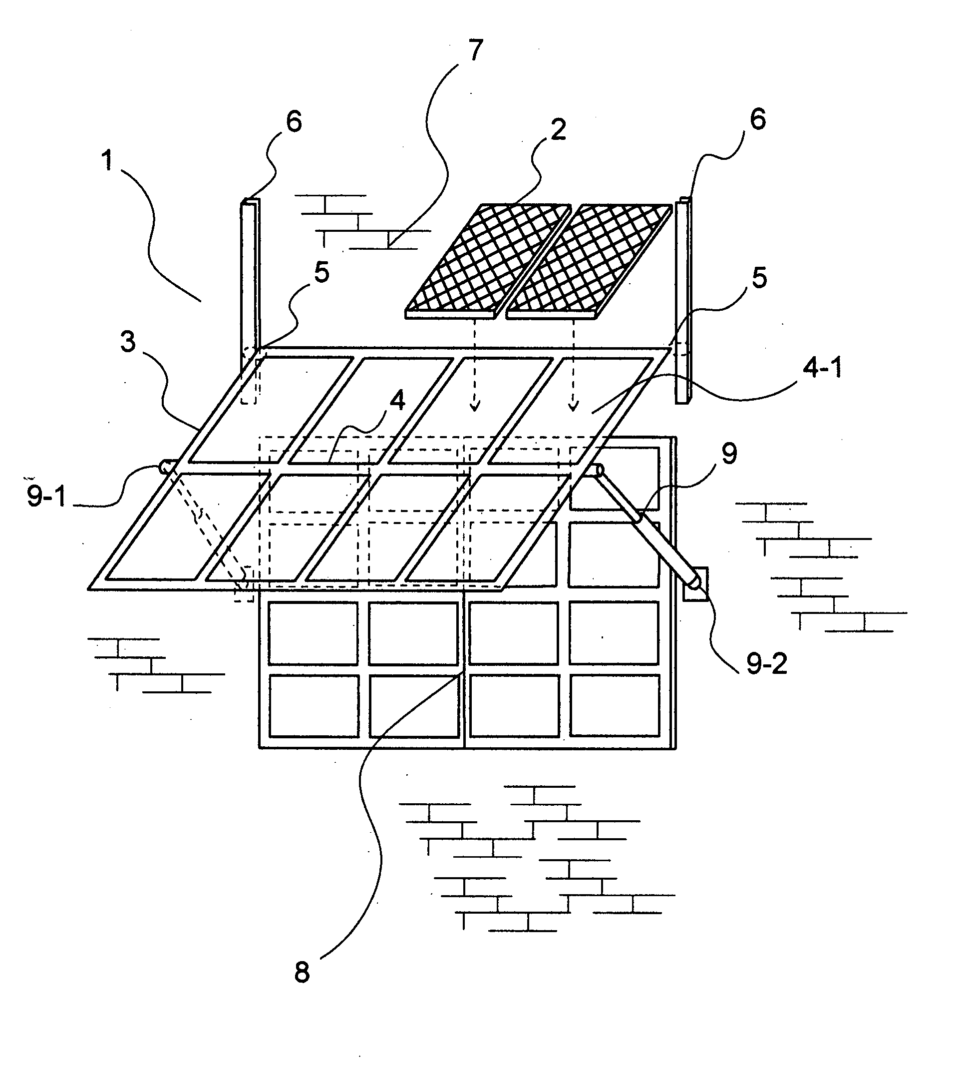
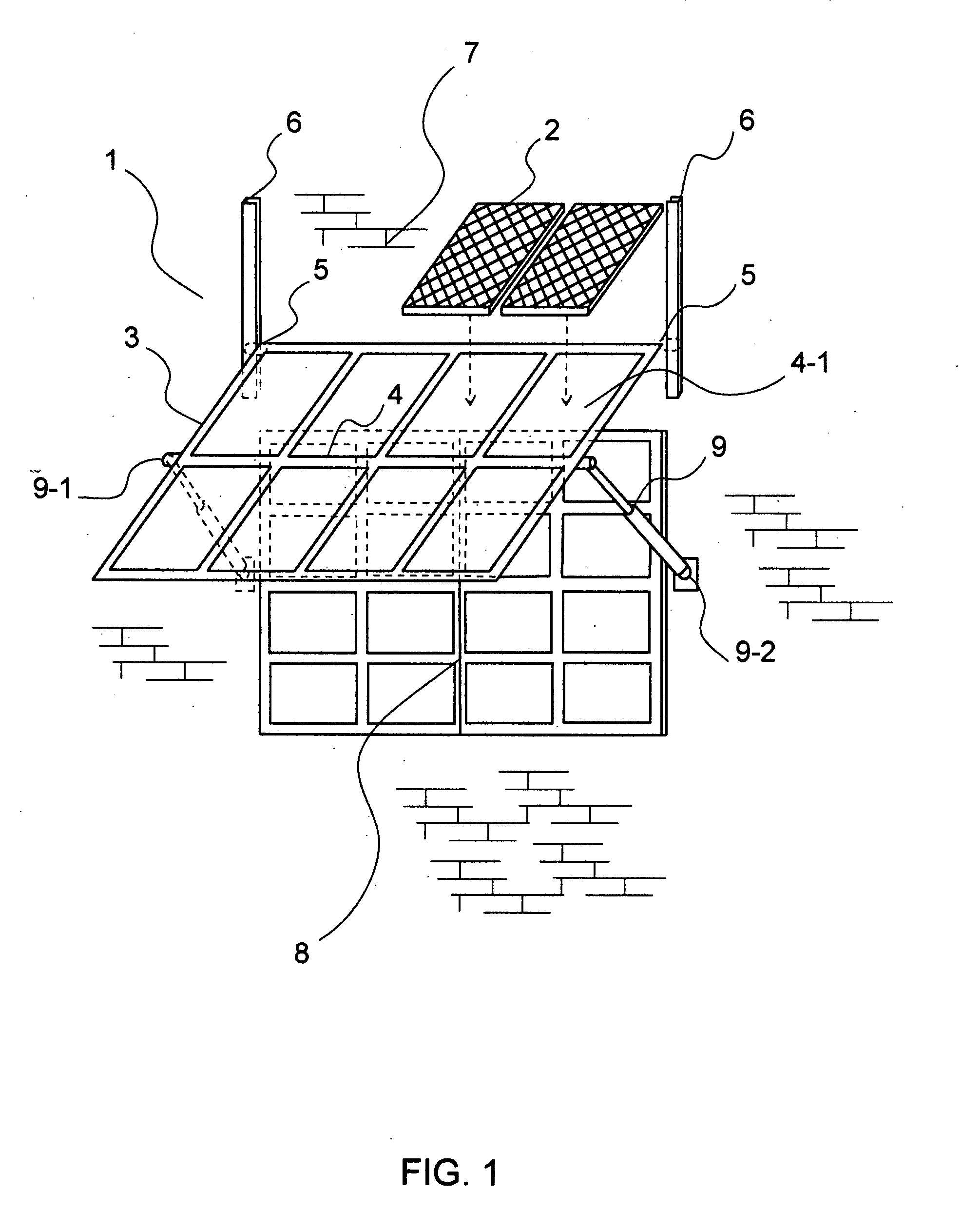
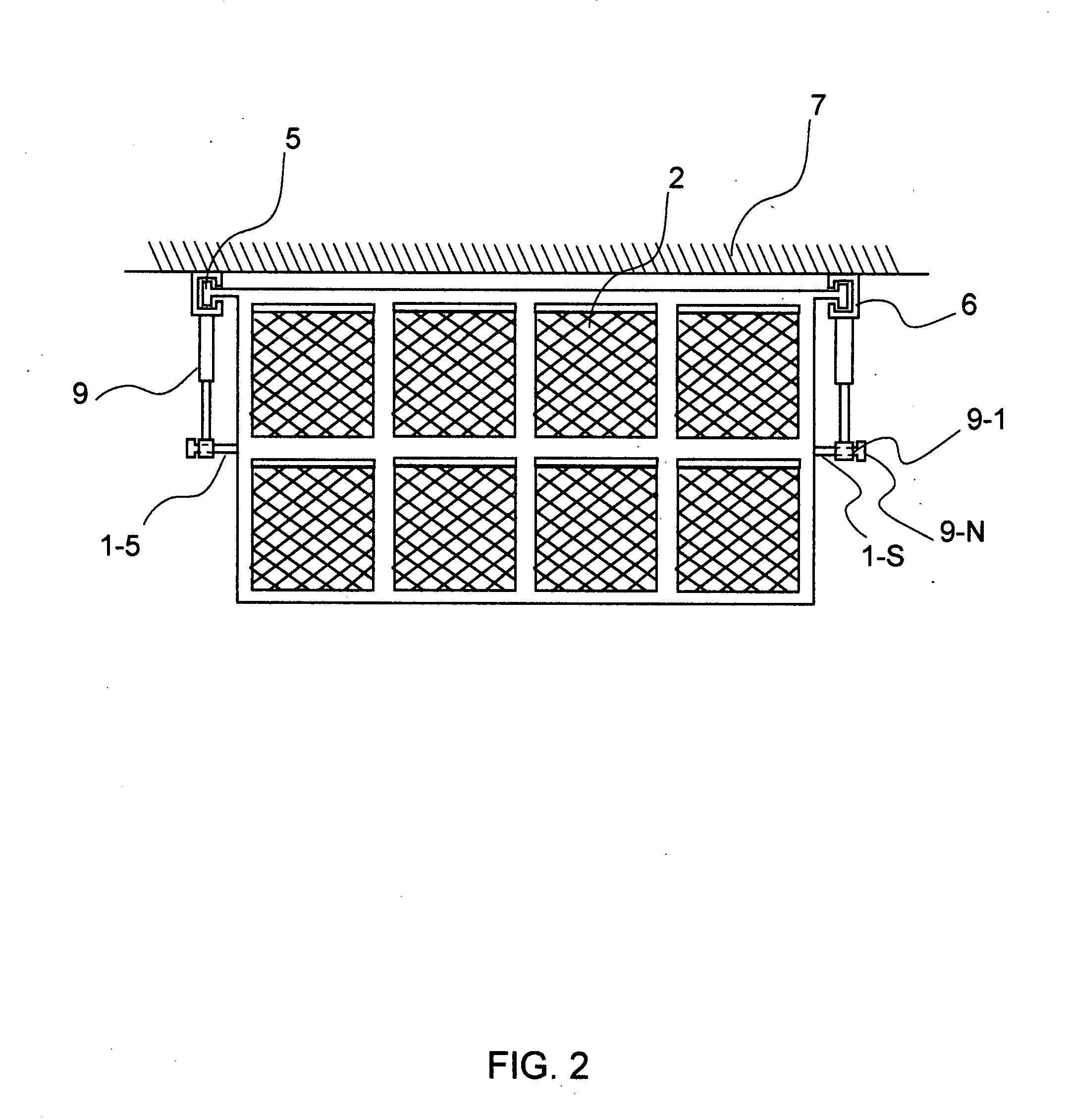
[0012]FIG. 1 is a perspective view of a solar cell plate (2) installed awning (1) according to current application. The awning (1) is comprised of a square metal frame (3) that has multiple square sectional divisions (4). FIG. 2 is a plan view of a solar cell plate (2) installed awning (1) according to current application. A wheel (5) is rotate-ably attached on each two corners (1-1) of the upper end of the square awning (1). Each wheel (5) is slide-ably engaged to a rail (6) that is fixed to a part of wall (7) that locates just above a window (8). Two telescopic supporting arms (9) connect both sides of the awing (1) and the wall (7). The upper end (9-1) of each telescopic supporting arm is rotate-ably connected to one side of the awning (1) in the middle and the lower end (9-2) of the supporting arm (9) is rotate-ably fixed to the wall (7) just beside the window (8). Each solar cell plate (2) is mounted on a section (4-1) of the awning (1). Electric wires are connected from the pl...


PUM


Abstract

An awning, equipped with pluralities of solar cell plates, is provided. The solar cell plates mounted awning can manually be positioned to follow the movement of the sun. The awning is comprised of a square metal frame that has multiple square sectional divisions. Solar cell plates are put on each division. Two wheels that rotate-ably attached on each corner of the upper end of the awning, two rails that are fixed to a part of wall above a window and two telescopic supporting arms connected both sides of the awing and the wall enables the awning to change the position according to movement of the sun. The owner of the house, who installed the awning, can enjoy the sunset outside the window while the awning absorbs the last of the sunlight to provide electricity for the appliances inside the room.

Description

1. FIELD OF THE INVENTION[0001]The current application relates to a metal awning structure with solar cell plates installed thereon, especially to an awning that can be adjusted manually according to the movement of the sun.2. BACKGROUND OF THE INVENTION[0002]Since the development of photovoltaic solar cell, many kinds of solar cells and methods of assembling the cells into a module, including the methods of assembling the solar cells for mounting on a house roof, have been introduced. Those methods teach only how to assemble each solar cell and the parts to connect them in a planar shape. According to those illustrations, a lot of heavy metal parts and ceramic insulators are necessary to make whole solar cell modules for mounting them on the roof of a house. The final solar cell module for a house may too heavy for the roof of a house. The heavy weight of the module limits the number of module plates that can be installed on a roof and the magnitude of the power that can be got fro...

Claims


Application Information

Patent Timeline
IPC IPC(8): H01L31/045E04F10/00
CPCE04F10/005E04F10/0603E04F10/0614F24J2/0444F24J2/541H02S20/00Y02B10/10Y02B10/20Y02E10/44Y02E10/47Y02E10/50F24J2002/5475H02S20/30H02S20/26F24S30/425F24S2030/14F24S20/66
Inventor OAK, EUGENE
Owner OAK EUGENE
Why Eureka
Try Eureka