Heat exchanger and its manufacturing method

a technology of heat exchanger and manufacturing method, which is applied in the direction of metal-working equipment, lighting and heating equipment, laminated elements, etc., can solve the problems of air current leakage and heat conversion efficiency drop, and achieve the effect of preventing air current leakage, enhancing mass productivity, and eliminating incorrect stacking of unit elements

Active Publication Date: 2009-02-05
PANASONIC CORP
View PDF5 Cites 45 Cited by
  • Summary
  • Abstract
  • Description
  • Claims
  • Application Information

AI Technical Summary

Benefits of technology

[0012]According to the heat exchanger and its manufacturing method of the present invention, enhancing mass productivity and preventing leakage of air current by eliminating incorrect stacking of the unit elements, and reducing manufacturing cost by reducing the number of components and reducing the number of processing steps are achieved.

Problems solved by technology

Since such conventional heat exchanger 109 is obtained by stacking spacer 101 and heat transfer plate 102 without joining the same, a problem arises in that leakage of air current increases due to lowering in sealing property caused by the shift in stacking, and thus prevention of the leakage of air current due to lowering in sealing property caused by the shift in stacking is demanded.
Thus, due to incorrect stacking of spacers 101, a problem arises in that heat conversion efficiency lowers due to the matter that the ventilation path cannot be correctly formed for every heat transfer plate 102.

Method used


Image

  • Heat exchanger and its manufacturing method
  • Heat exchanger and its manufacturing method
  • Heat exchanger and its manufacturing method

Examples


first embodiment

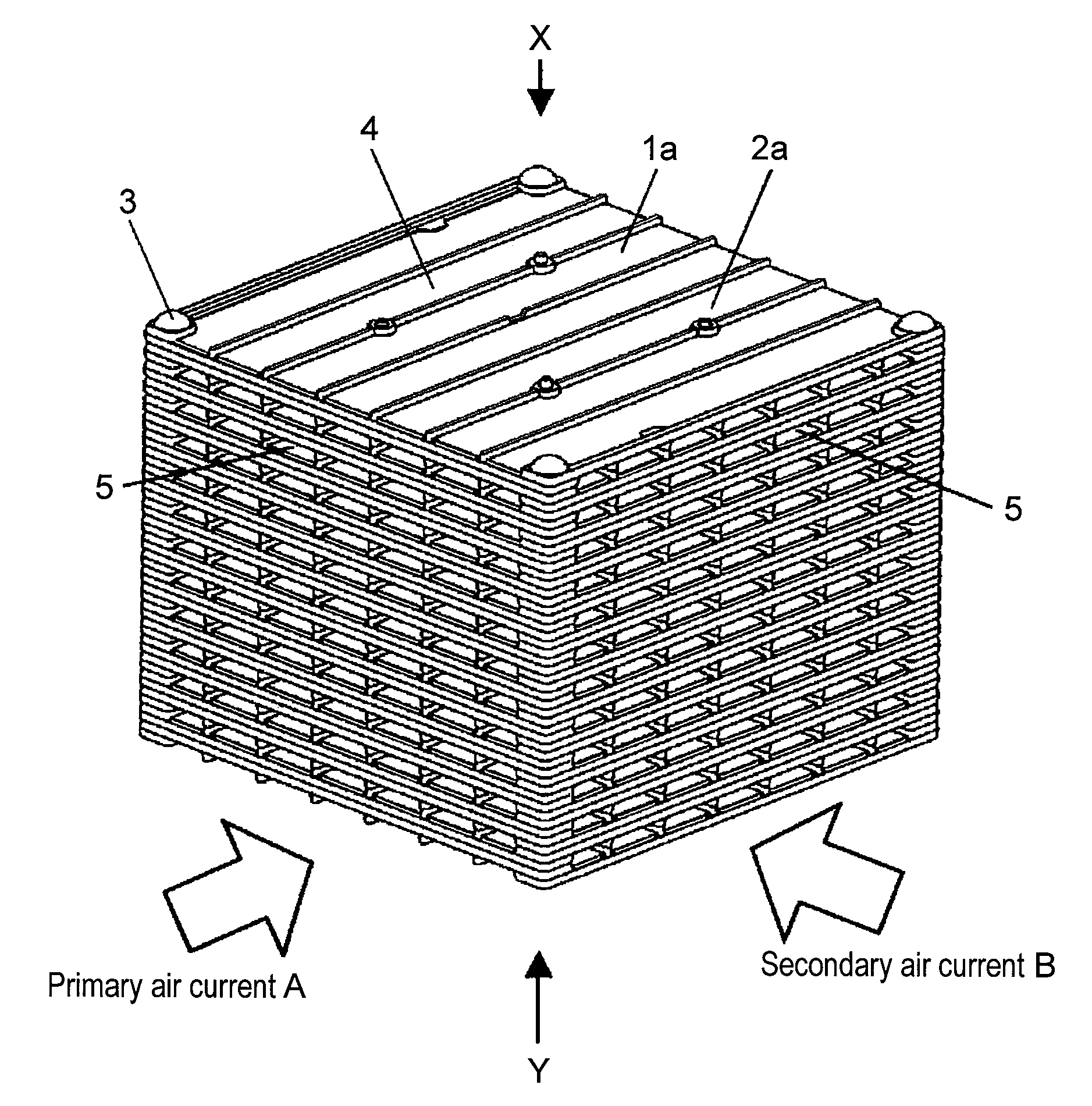
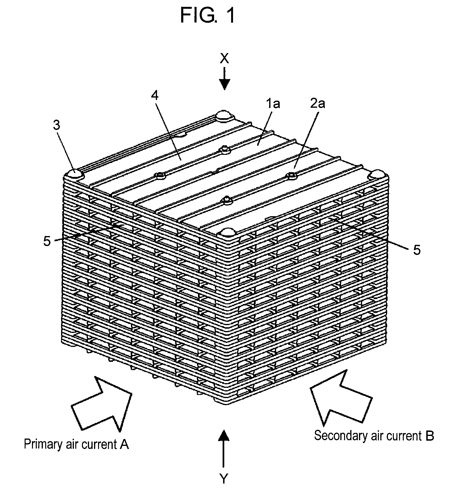
[0094]FIG. 1 is a schematic perspective view of a heat exchanger according to the first embodiment, FIG. 2A is a schematic perspective view of a unit element seen from an X-direction shown in FIG. 1, and FIG. 2B is a schematic perspective view of the unit element seen from a Y-direction shown in FIG. 1. FIG. 3 is a schematic exploded perspective view of the heat exchanger shown in FIG. 1. FIG. 4A is a schematic perspective view of the heat exchanger in which the unit elements of the heat exchanger shown in FIG. 1 are correctly stacked, FIG. 4B is a schematic perspective view of the heat exchanger taken along line 4B-4B shown in FIG. 4A, and FIG. 4C is a schematic enlarged perspective view of a circled portion in FIG. 4B. FIG. 5A is a schematic perspective view of the heat exchanger in which the unit elements of the heat exchanger shown in FIG. 1 are incorrectly stacked, and FIG. 5B is a schematic enlarged perspective view of a circled portion in FIG. 5A.

[0095]FIG. 6A is a schematic ...

second embodiment

[0163]FIG. 14 is a schematic perspective view of a heat exchanger according to the second embodiment, FIG. 15A is a schematic perspective view of a unit element seen from an X-direction shown in FIG. 14, and FIG. 15B is a schematic perspective view of the unit element seen from a Y-direction shown in FIG. 14. FIG. 16A is a schematic perspective view of the heat exchanger in which the unit elements of the heat exchanger shown in FIG. 14 are correctly stacked, FIG. 16B is a schematic perspective view of the heat exchanger taken along line 16B-16B shown in FIG. 16A, and FIG. 16C is a schematic enlarged perspective view of a circled portion in FIG. 16B.

[0164]FIG. 17A is a schematic perspective view of the heat exchanger in which the unit elements of the heat exchanger shown in FIG. 14 are incorrectly stacked, FIG. 17B is a schematic perspective view of the heat exchanger taken along line 17B-17B shown in FIG. 17A, and FIG. 17C is a schematic enlarged perspective view of a circled portio...


PUM

PropertyMeasurementUnit
thicknessaaaaaaaaaa
thicknessaaaaaaaaaa
widthaaaaaaaaaa

Abstract

A heat exchanger for exchanging heat through a heat transfer plate by flowing a primary air current and a secondary air current to a ventilation path is provided. An unit element including the heat transfer plate, and the ventilation path formed between the heat transfer plates by stacking the unit element in plural are arranged. The unit element is configured by integrally molding a spacing rib for holding a spacing of the heat transfer plate, and a shield rib for shielding leakage of the air current with resin. Furthermore, the unit element includes a stacking error detecting unit for determining a stacking error when they are stacked.

Description

TECHNICAL FIELD[0001]The present invention relates to a heat exchanger of a laminated structure used in a home heat exchange ventilation fan, a total heat exchange ventilator in a building etc., and its manufacturing method.BACKGROUND ART[0002]This type of heat exchanger conventionally includes a heat exchanger formed by stacking a heat transfer plate and a spacer without bonding in order to suppress the manufacturing cost while enhancing the basic function such as ventilation resistance and heat conversion efficiency. This is disclosed in patent document 1 and the like. The heat exchanger will be described below with reference to FIG. 20A, FIG. 20B, and FIG. 21.[0003]As shown in such figures, spacer 101 made of synthetic resin includes spacing rib 103 for holding a spacing between heat transfer plates 102, coupling rib 104 for coupling spacing ribs 103, and small projection 105 arranged on spacing rib 103 and coupling rib 104. The opposing surfaces of the spacer stacked one above t...

Claims


Application Information

Patent Timeline
Patent Type & Authority Applications(United States)
IPC IPC(8): F28F3/08B21D53/02
CPCF28D9/0037Y10T29/4935F28F3/08F28F2280/04
Inventor MURAYAMA, TAKUYA
Owner PANASONIC CORP
Why Eureka
Try Eureka