
Umbilical-member processing structure for industrial robot

Active Publication Date: 2009-02-05
FANUC LTD
View PDF17 Cites 18 Cited by
  • Summary
  • Abstract
  • Description
  • Claims
  • Application Information

AI Technical Summary

Benefits of technology

[0008]It is an object of the present invention to provide an umbilical-member processing structure for an industrial robot that is capable of stabilizing the behavior of the umbilical-member disposed along the wrist and increasing the reliability of the connection of the umbilical-member even when the work tool and the wrist are moved in complex movement.
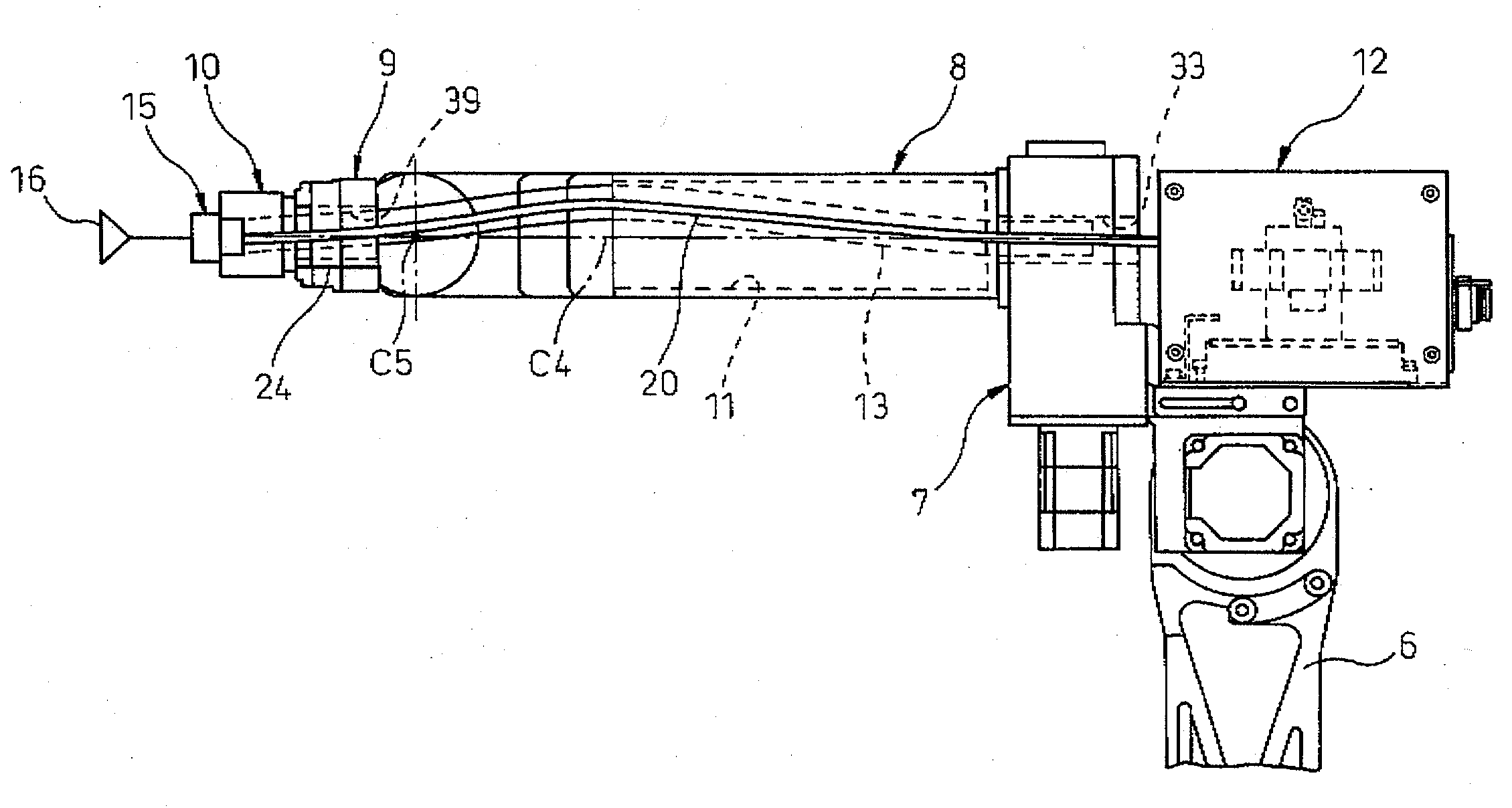
[0010]With the construction as described above, since the other end of the conduit for passing the umbilical-member is held on the second wrist element in cantilever fashion, no excessive force is exerted to the conduit even when the wrist elements are operated, so that durability of the conduit is improved. The umbilical-member for the work tool is passed inside the conduit, and since diameter of umbilical-member is often small, the movement of the umbilical-member in the inner space of the conduit can absorb the bending and twisting during the operation of the wrist elements. The support structure of the conduit is simple and allows replacement of the umbilical-member in the conduit to be carried out easily. A user can freely pass a desired umbilical-member suitable for the work tool through the conduit as long as the size of the umbilical-member is smaller than the inner diameter of the conduit. Thus, the behavior of the umbilical-member in the conduit can be stabilized and the reliability of the connection of the umbilical-member can be improved.
[0011]In the umbilical-member processing structure for industrial robot as described above, it is also possible to construct it such that the conduit has a ring-shaped groove on an outer circumferential surface, and the conduit holding member has a convex portion on an inner surface to be engaged with the groove, such that, when the convex portion is engaged with the groove to hold the conduit with the conduit holding-member, the conduit is held in the cantilever fashion by the second wrist element so as to permit the rotation of the conduit in the outer circumferential direction. Engagement of the convex portion of the conduit holding member with the groove of the conduit allows the other end of the conduit to be held on the second wrist element rotatably about the rotation axis of the first wrist element, so that the conduit can be protected from the action of twist due to rotation of the first wrist element, and durability of the conduit can be thereby increased.
[0012]In the umbilical-member processing structure for industrial robot as described above, it is also possible to construct it such that the end of the conduit inserted in the first insertion hole is covered by a tubular pipe member. With such construction, it becomes possible, when bending is produced by the wrist operation, to move the conduit in reciprocating motion in the axial direction more smoothly. Sometimes, the conduit may have an innate tendency of bending for some reason related to the manufacture, or the extra length of the conduit path may be offset relative to the conduit axis, thus leading to a small twist acting on the conduit when the second wrist element is rotated. If the diameter of the umbilical-member in the conduit is large, the umbilical-member may be subjected to a twisting force when the third wrist element is rotated, and may be deformed in spiral form over the entire length of the umbilical-member. Even in such a case, since the conduit is slidingly rotated, the umbilical-member is free from any excessive force and can move smoothly.

Problems solved by technology

However, although a conduit can absorb bending, it cannot absorb twisting adequately, and therefore, it is necessary to provide a rotatable support member on either end of the conduit.
Although it is possible to provide a rotatable support member on the outer circumference of the conduit, there is a problem that the size of the wrist and the forearm needs to be increased in order to pass the conduit therethrough.
This has a disadvantage that the load imposed on the robot is increased and the interference with the peripheral equipments is more likely to happen.
However, on the side of the work tool, it may be necessary to change the attitude of the work tool in accordance with the intended work, and there is a problem that, the farther the mounting position of the work tool becomes, the narrower and the more confined the range of possible attitude of the robot in the operating region becomes.

Method used


Image

  • Umbilical-member processing structure for industrial robot
  • Umbilical-member processing structure for industrial robot
  • Umbilical-member processing structure for industrial robot

Examples


Embodiment Construction

[0039]The present invention will be described in detail with reference to drawings.

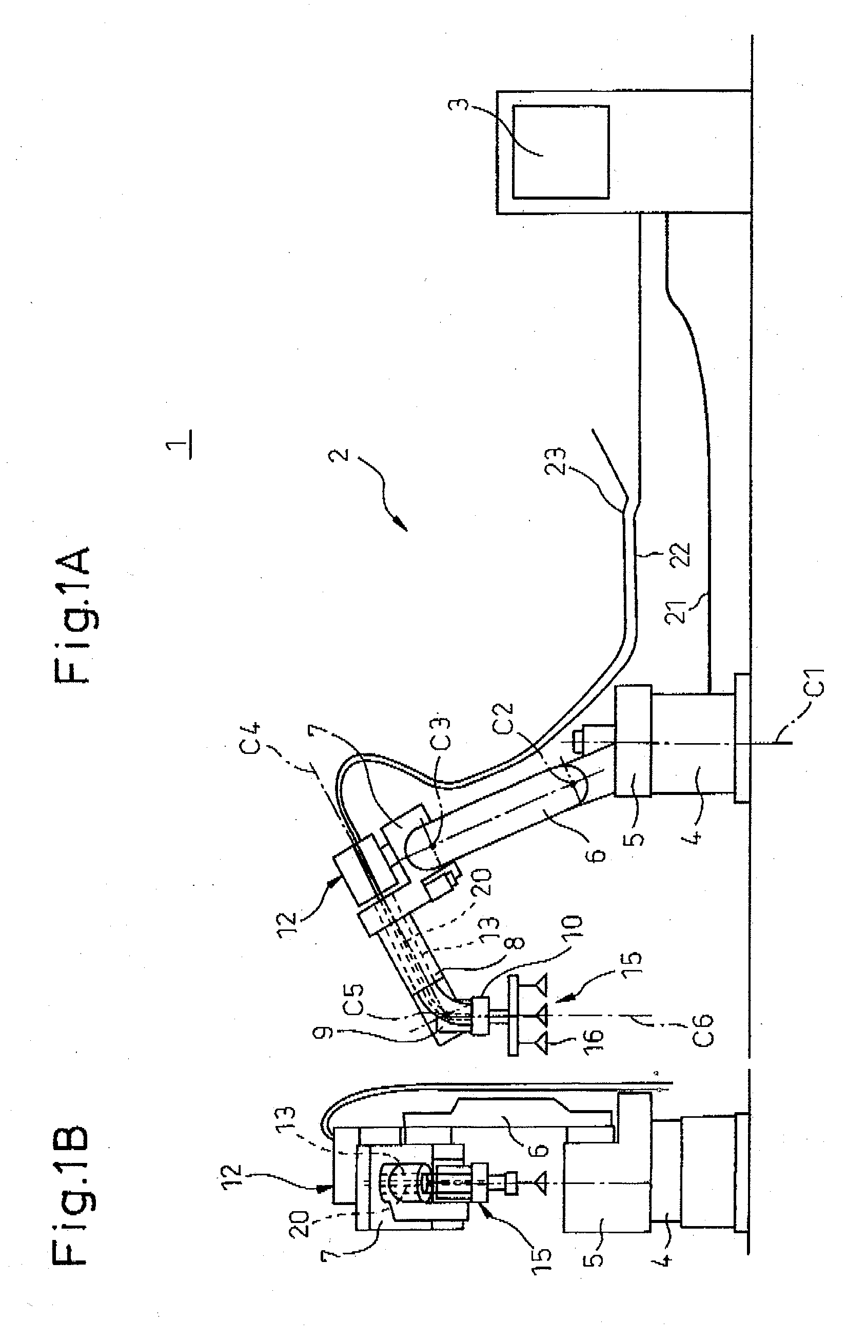
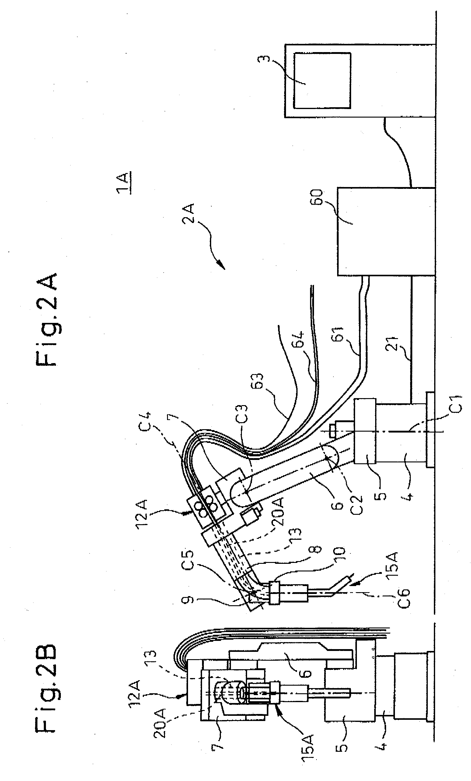
[0040]FIGS. 1A, B are views of a handling robot system having a work tool. An umbilical-member (hand cable) connected to the work tool (hand) is passed inside a forearm and first to third wrist elements. FIGS. 2A, B are views of an arc welding robot system as another example of an umbilical-member (torch cable) connected to a work tool (welding torch) being passed inside a forearm and first to third wrist elements.

[0041]Robot 2 shown in FIGS. 1A, B is a handling robot of six-axes of freedom comprising swivel trunk 5 rotated about a first rotation axis on base 4 of a robot body, upper arm 6 connected rotatably about a second rotation axis to an upper portion of swivel trunk 5, forearm 7 rotatably connected about a third rotation axis to a distal end of upper arm 6, and a wrist having three axes of freedom. The wrist consists of a first-third wrist elements 8-10. Robot 2 is controlled in accordance with...


PUM


Abstract

An umbilical-member processing structure for an industrial robot which includes a forearm having a tool managing and relaying device and a wrist with proximal end rotatably connected to the forearm and having a work tool mounted on the distal end thereof, with an umbilical-member connected to the work tool being disposed to run along the wrist via the tool managing and relaying device: wherein the forearm has a first reduction gear which reduces the rotational speed of a driving source to drive the forearm in rotation; the first reduction gear having a first insertion hole for passing the umbilical-member therein; and wherein the wrist comprises a first wrist element having a through-path in communication with the first insertion hole and rotatably connected to the forearm, and a second wrist element having a second insertion hole in communication with the through-path and rotatably connected to the first wrist element; and wherein a conduit for passing the umbilical-member from one end to the other end is provided in the first insertion hole of the forearm, in the through-path of the first wrist element, and in the second insertion hole of the second wrist element; and wherein, with one end of the conduit being inserted in the first insertion hole so as to permit movement in an axial direction and in a direction of outer circumference of the conduit, the other end of the conduit is held on the second wrist element in cantilever fashion by a conduit holding member so as to restrict movement of the conduit in the axial direction thereof.

Description

CROSS REFERENCE TO RELATED APPLICATIONS[0001]The present application claims the benefit of priority based on Japanese Patent Application No. 2007-197752, filed on Jul. 30, 2007, disclosure of which is incorporated herein in its entirety by reference.BACKGROUND OF THE INVENTION[0002]1. Field of the Invention[0003]The present invention relates to an umbilical-member processing structure for an industrial robot in which an umbilical-member connected to a work tool that is mounted on a distal end of a wrist, are disposed to run along the wrist via a tool managing and relaying device mounted on a forearm.[0004]2. Description of Related Art[0005]In general, as an industrial robot in which an umbilical-member connected to a work tool, are disposed to run along a wrist, a so-called umbilical-member-containing robot having the umbilical-member passed inside a hollow portion of the forearm and inside the wrist is disclosed in Japanese Patent Publication No. 2005-271003. In this case, in order...

Claims


Application Information

Patent Timeline
IPC IPC(8): F16L3/00
CPCB25J17/0283B25J19/0029Y10T74/20335H02G11/00Y10T74/20311F16L3/1091
Inventor INOUE, TOSHIHIKONAKAYAMA, KAZUTAKAIWAYAMA, TAKATOSHI
Owner FANUC LTD
Learn More