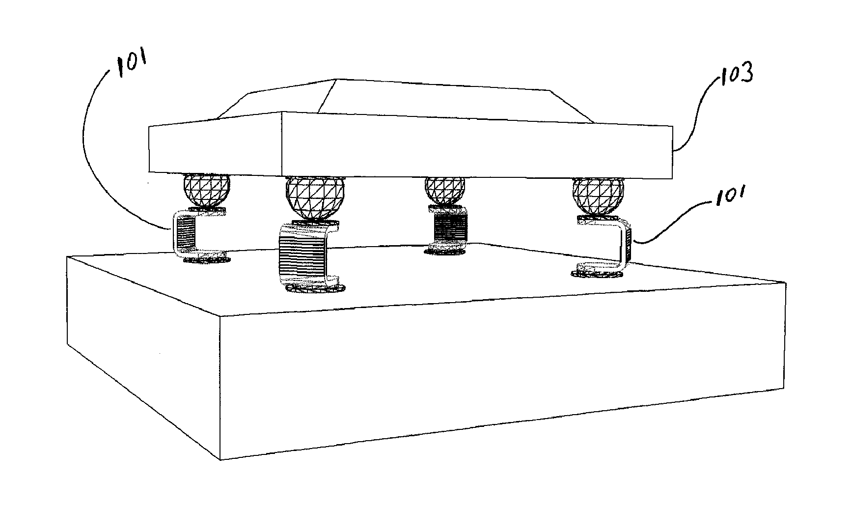
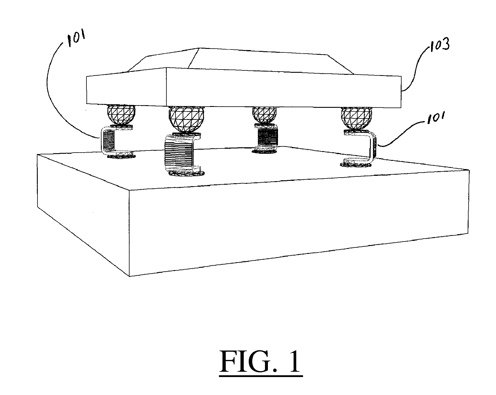
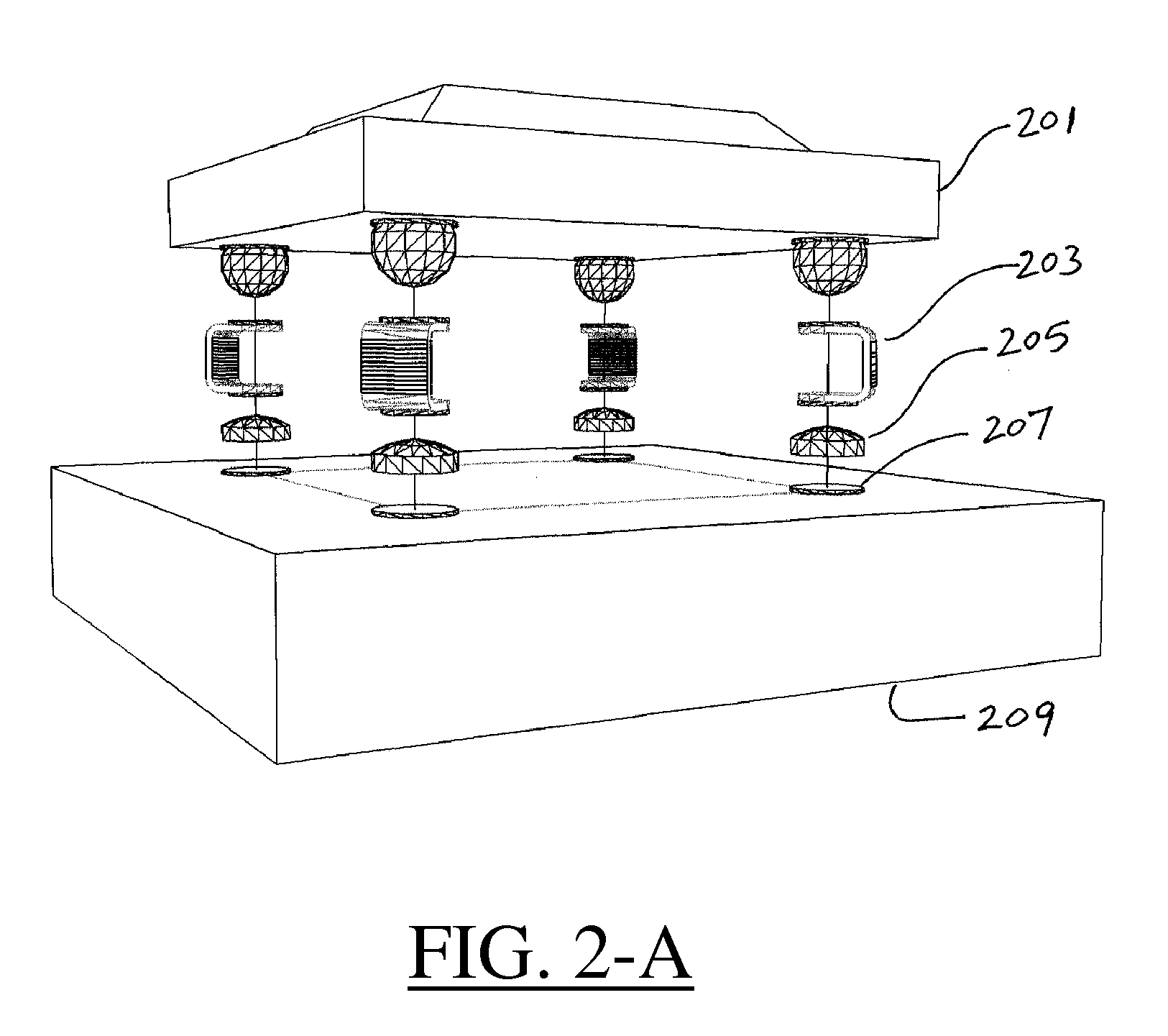
Al technical title is built by PatSnap Al team. It summarizes the technical point description of the patent document.
a contact carrier and thermal flex technology, applied in the direction of printed circuit aspects, sustainable manufacturing/processing, final product manufacturing, etc., can solve the problems of premature failure of interconnection joints, many components are being miniaturized, and the right thing to do with direct sintering of components to substrates or pcbs, etc., to reduce the stress on columns
Inactive Publication Date: 2009-02-05
CHERIAN GABE
View PDF5 Cites 7 Cited by
Summary
Abstract
Description
Claims
Application Information
AI Technical Summary
This helps you quickly interpret patents by identifying the three key elements:
Problems solved by technology
Method used
Benefits of technology
[0034]The general object of the invention is to introduce certain changes and / or improvements in the way Integrated Circuit (IC) Packages known as BGAs, Ball Grid Array Packages and other similar leadless devices and chips, and assemblies that incorporate such packages and / or chips, so that they become more reliable and can better withstand the above undesirable effects of thermal cycling and power cycling. The same proposed changes would also make such assemblies, more reliable and would enable them to better withstand stresses induced by shock and vibrations.
[0079]Orient the columns in a way to reduce their resistance to bending, when the system is exposed to thermal fluctuations.
Problems solved by technology
In the case of leadless electronic components, like the BGAs and the LCCCs, it has been known that soldering such components directly to substrates or to PCBs is not the right thing to do.
It can lead to premature failure of the interconnecting joints.
The problem results mostly from exposing electronic assemblies to varying temperatures, such as thermal cycling or power cycling, or simply from being exposed to harsh environment, including hot and cold temperature environment This is especially true, when the component is relatively large, when the material of the component is different than that of the substrate, and with different TCEs, i.e. with TCE Mismatch, and when the temperature fluctuates considerably and frequently during the life of the assembly.
The additional problem nowadays is the fact that many of the components are being miniaturized.
The center distances between contact pads are getting smaller and smaller, and the old inventions can no longer keep up with such miniaturization.
Cherian Solder Columns cannot readily be simply scaled down to size.
On the other hand, if the stresses are in an unfavorable direction, then the package may fail.
Method used
Image
Click on the blue label to locate the original text in one second.
Reading with bidirectional positioning of images and text.
Examples
Embodiment Construction
[0083]While the invention is susceptible of various modifications and alternative constructions, certain illustrative embodiments thereof have been shown in the drawings and will be described below in detail. It should be understood, however, that there is no intention to limit the invention to the specific form disclosed, but, on the contrary, the invention is to cover all modifications, alternative constructions and equivalents, falling within the spirit and scope of the invention as defined in the claims.
[0084]While I am describing the drawing in more details, I will at the same time explain the technology basis of the invention. I will also include a number of examples in this section, which should be considered as part of the embodiments for the purpose of this application as well.
[0085]This description covers more than one invention. The inventions are based partly on the same technology platform, but then each of the inventions has some additional features of its own. Not bei...
PUM
Abstract
Two groups of interconnection devices and methods are described. Both provide columns between electronic packages and boards or between chips and substrates or the like. In the first group, called Thermal Flex Contact Carrier (TFCC), the column elements are carved out of a flat laminated structure and then formed to suit. In the second group, the carrier, which carries the connecting elements, is made out of a soluble or removable material, which acts at the same time, as a solder mask, to prevent the solder from wicking along the stem of the elements.
Description
CROSS-REFERENCE TO RELATED APPLICATIONS[0001]This application is a NON-PROVISIONAL UTILITY PATENT APPLICATION, and should be considered as a CONTINUATION PATENT APPLICATION, based on patent application Ser. No. 11 / 689,558, filed Mar. 22, 2007, title “NO-WICK™ 2 INTERCONNECTIONS”, which is a Divisional Patent Application based on patent application Ser. No. 10 / 937,647, filed Sep. 8, 2004, title “INTERCONNECTIONS”, now U.S. Pat. No. 7,196,402 issued Mar. 27, 2007, which in turn is a DIVISIONAL Patent Application, based on patent application Ser. No. 10 / 075,060, filed Mar. 17, 2003, title “INTERCONNECTIONS”, now U.S. Pat. No. 6,884,707, issued Apr. 26, 2005.[0002]This application is claiming the priority and benefits of the following prior applications, which include the same references, which were claimed by the two mother applications. These prior applications are the following seven patent applications, where three are provisional patent applications and four non-provisional utility...
Claims
Application Information
Patent Timeline
Application Date:The date an application was filed.
Publication Date:The date a patent or application was officially published.
First Publication Date:The earliest publication date of a patent with the same application number.
Issue Date:Publication date of the patent grant document.
PCT Entry Date:The Entry date of PCT National Phase.
Estimated Expiry Date:The statutory expiry date of a patent right according to the Patent Law, and it is the longest term of protection that the patent right can achieve without the termination of the patent right due to other reasons(Term extension factor has been taken into account ).
Invalid Date:Actual expiry date is based on effective date or publication date of legal transaction data of invalid patent.
Patent Type & Authority Applications(United States)