Position Detector

a position detector and detector technology, applied in the field of position detectors, can solve the problems of reducing the sliding ability, increasing the cost of positioning detectors, and increasing the number of appliances using position detectors, so as to reduce the width of the track, increase the magnetic field, and reduce the magnetic flux

Inactive Publication Date: 2009-02-05
YAMAHA CORP
View PDF2 Cites 4 Cited by
  • Summary
  • Abstract
  • Description
  • Claims
  • Application Information

AI Technical Summary

Benefits of technology

[0036]According to one aspect of the invention, it is not necessary to provide a separate track for the detection of the origin point, thereby reducing a width of the track by half as compared to the conventional device. Further, the magnetizing process of the scale part is necessary only once, and a separate magnetic sensor dedicated to the origin point detection is unnecessary.
[0037]Further, according to another aspect of the invention, there is provided a position detector which can perform stable and appropriate sensing where the detection of the origin point and the detection of the direction and displacement are integrated by a common magnetic sensor.
[0038]The invention features that the scale part is strongly magnetized to increase the magnetic field while the magnetic field shaping part is provided for shaping a spatial distribution of the magnetic field to thereby reduce a magnetic flux which enters into the magnetic detection part and forming an efficient guard field along sides of the magnetic scale part. First, by intensively magnetizing the scale part, it is possible to avoid r

Problems solved by technology

However, difficulties in managing the gap between the magnetic scale and the magnetic sensor are on the rise.
In the conventional method of detecting the origin point, a magnetic mark for origin point detection is provided on a separate channel, hence a magnetic sensor for detecting the origin point must be provided separately from another magnetic sensor for scaling, thereby causing problems such as over-size of the position detector which causes enlargement of appliances using the position detector and increase of costs.
Slidability is degraded if the clearance is set to be as small as possible, whereas loss of sensing pulses or jouncing may occur if the clearance is set too large.
However, the gap between the magnetic scale and the magnetic sensor opposing each other may be reduced below a critical level due to a variety of reasons such as uneven clearance within a slide range due to aging.
In this case, it is difficult to obtain a resolution of signals having a logic value “0” or “1” when employing a method in which an origin, which is a Z phase representing the reference point of the magnetic scale

Method used


Image

  • Position Detector
  • Position Detector
  • Position Detector

Examples


first embodiment

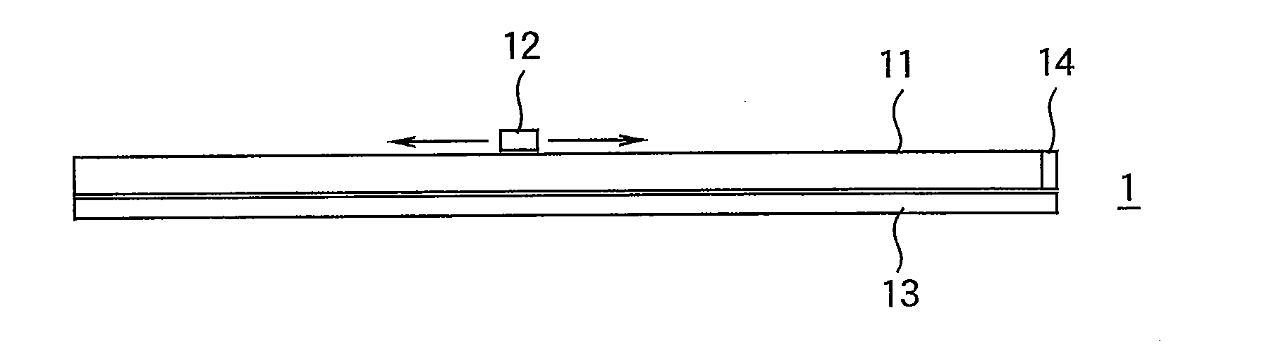
[0053]FIGS. 1A and 1B are schematic side views illustrating a basic configuration of a position detector (magnetic scale) 1 according to the invention. Specifically, FIG. 1A is a longitudinal side view of the magnetic scale 1 and FIG. 1B is a transversal side view of the magnetic scale 1.

[0054]The magnetic scale 1 includes a magnetic scale member (magnetic scale part) 11, a magnetic sensor (magnetic detection part) 12, and a magnetic field shaping member (magnetic field shaping part) 13.

[0055]For example, the scale member 11 is a bar-shaped member formed of a permanent magnet such as a ferrite magnet including a metal compound or a rubber magnet formed by mixing ferrite magnetic powder, rubber material, etc. The scale member 11 may also be formed by filling a groove in a stainless bar (for example, having a radius of 4.0 to 8.0 mm) with a long and thin rubber magnetic filler (for example, having a radius of 1.5 to 5.0 mm) and then magnetizing the magnetic filler from a top 11a, usin...

third embodiment

[0084]FIG. 9 is a schematic plan view illustrating a basic configuration of a position detector (magnetic scale) 2 according to the invention.

[0085]This embodiment differs from the first embodiment in that a magnetic field shaping member 23 formed of a permanent magnet is disposed near an end portion of the scale member 11 instead of disposing the magnetic field shaping member 13 throughout the entire length of the scale member 11. Other aspects of the basic configuration of the magnetic scale are similar to those of the first embodiment and thus a description thereof is omitted herein.

[0086]In the position detector (magnetic scale) 2 according to the third embodiment, it is necessary to perform a process for extracting an origin forming signal since the magnetic field shaping member 23 is mounted only at the end portion of the scale member as described above. Therefore, a scale signal A and an origin forming signal B are XORed as shown in FIG. 10 and an XOR signal initially output ...

fourth embodiment

[0087]As shown in a timing chart of FIG. 10, as the magnetic sensor 12 is moved toward the end portion of the scale member 11, origin forming signals disappear upon entering a specific section, and an origin forming signal B that is first detected after origin forming signals disappear can be determined to be a genuine origin forming signal, provided that a plurality of scale signals is present in the specific section where no origin forming signal is present. Processes in this case will be described below in the invention. A right end portion of the signal A in FIG. 10 is disregarded since it corresponds to a right end portion of the analog signal in FIG. 6 and a right end portion of the signal A based on the analog signal in FIG. 6 while it represents an inaccurately magnetized portion of the end portion of the scale member 11.

[0088]FIG. 11 is an exploded perspective view of a main part of a slide volume device 3 according to the fourth embodiment of the invention. Components simi...


PUM


Abstract

In a position detecting apparatus, a magnetic scale part has a magnetic pattern formed by magnetization along a longitudinal direction. An increased magnetization part is arranged at an end portion of the magnetic scale part in the longitudinal direction. The increased magnetization part is magnetized with an increased intensity of magnetization as compared to the magnetic scale part. A magnetic field shaping part is disposed adjacent to the magnetic scale part for shaping a magnetic field generated from the magnetic scale part. A magnetic detection part detects both the magnetic field from the magnetic pattern of the magnetic scale part and the magnetic field from the increased magnetization part. The magnetic detection part is arranged in opposed relation to the magnetic scale part movably in the longitudinal direction of the magnetic scale part. The magnetic pattern and the increased magnetization part are arranged along a track through which the magnetic detection part moves.

Description

BACKGROUND OF THE INVENTION[0001]1. Technical Field of the Invention[0002]The present invention relates to a position detector, and more particularly to a position detector using a magnetic scale member.[0003]2. Description of the Related Art[0004]A magnetic scale sensing apparatus using a position detector (magnetic scale), which includes a magnetic sensor using a magnetoresistance (MR) element or the like and a scale member which is magnetically patterned, has been known as an origin detection device of a magnetic encoder.[0005]To determine the position of the magnetic sensor, the magnetic scale sensing apparatus needs to detect the position of an origin of the scale. In one known origin detection method, a magnetic mark for origin detection is provided in a channel different from that of the scale member, and the origin is determined by detecting the magnetic mark (for example, see Patent Document 1). In the conventional method of detecting the origin point, a magnetic mark for o...

Claims


Application Information

Patent Timeline
IPC IPC(8): G01B7/14
CPCG01B7/003
Inventor HAYASHI, YOSHINORI
Owner YAMAHA CORP
Why Eureka
Try Eureka