
Mobile communication terminal having projector

Inactive Publication Date: 2009-02-05
SAMSUNG ELECTRONICS CO LTD
View PDF6 Cites 25 Cited by
  • Summary
  • Abstract
  • Description
  • Claims
  • Application Information

AI Technical Summary

Benefits of technology

[0011]The present invention overcomes the limitations of the prior art by providing a mobile communication terminal having a projector and a partition structure for preventing heat generated from electronic elements thereof from being influenced on the projector.
[0012]Also, the present invention provides a mobile communication terminal having a projector and a heat-dissipation structure having an enlarged effective area for effectively dissipating heat generated from the projector without using a fan.

Problems solved by technology

However, such a mobile communication terminal having a projector function generates a great quantity of heat from its internal elements because it has multiple heat sources, such as a light-emitting element of a projector and other elements for implementing mobile communication.
Further, the luminous element such as the LED or LD is more vulnerable to detrimental effects of heat than other electronic products because temperature changes can cause variation in output characteristics.
Thus, if heat that is generated when the mobile communication terminal having the projector is driven is not efficiently dissipated, the performance of the light source of the illuminating system degrades, and the lifetime of an internal element is shortened due to over-heating in the terminal.
Conventional heat-managing methods are effective only for preventing the heat source from excessively overheating, but are not intended to effectively dissipate heat.
However, while the compulsive heat dissipation is effective for the case of the heat source, such as the projector generating high temperature, it is hardly adapted to the mobile communication terminal.
This would have the undesirable effect of altering the mobile terminal so that the size is enlarged, would require additional power to run the fan, and increase the occurrence of unwanted noise at the same time.
In addition, in the case of trying to use natural heat-radiation, the mobile communication terminal cannot effectively radiate heat because, due to its limited size, it has a limited potential radiation area.

Method used


Image

  • Mobile communication terminal having projector
  • Mobile communication terminal having projector
  • Mobile communication terminal having projector

Examples


Embodiment Construction

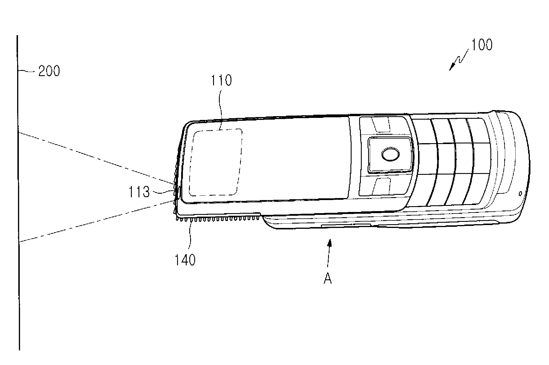
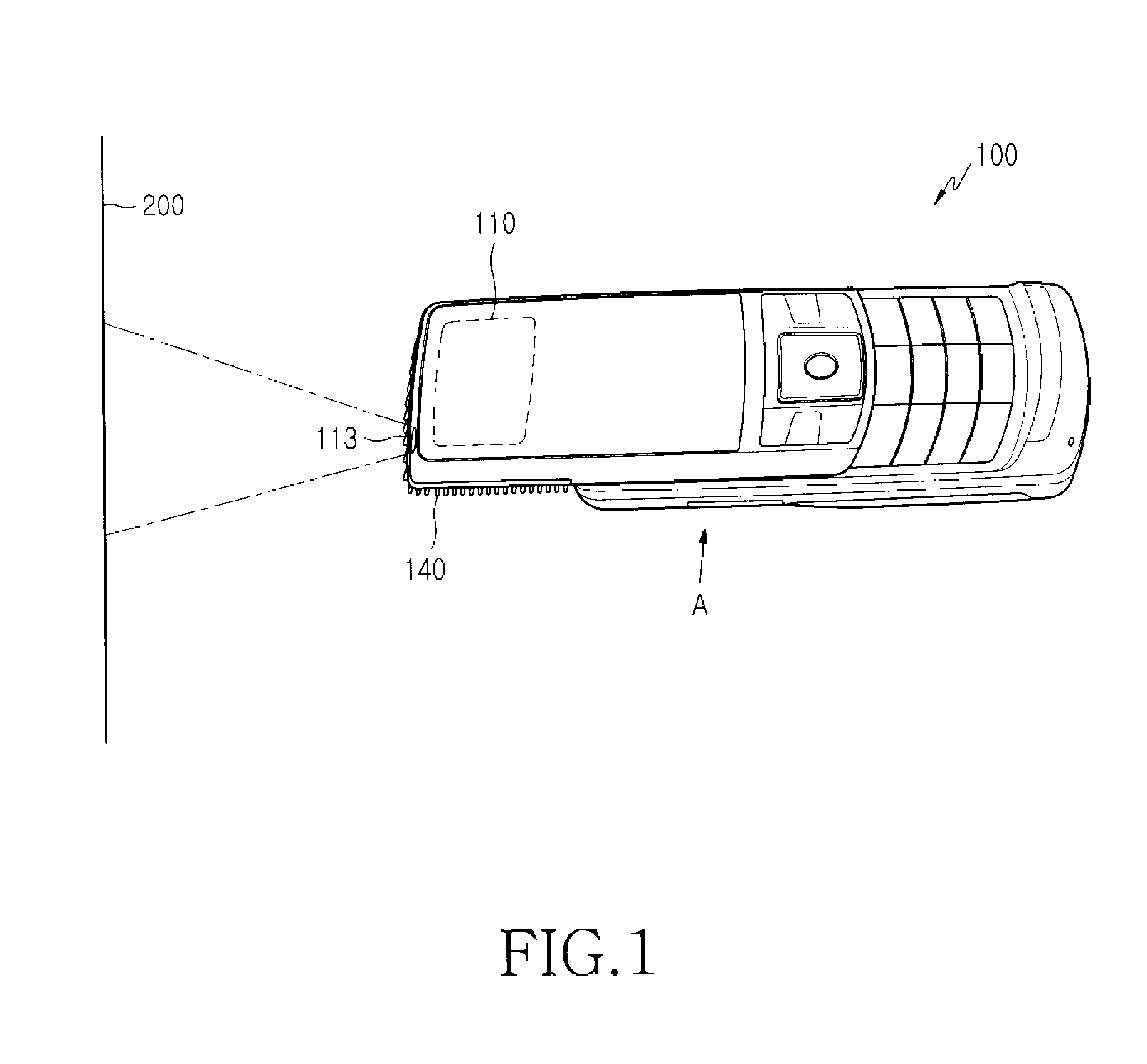
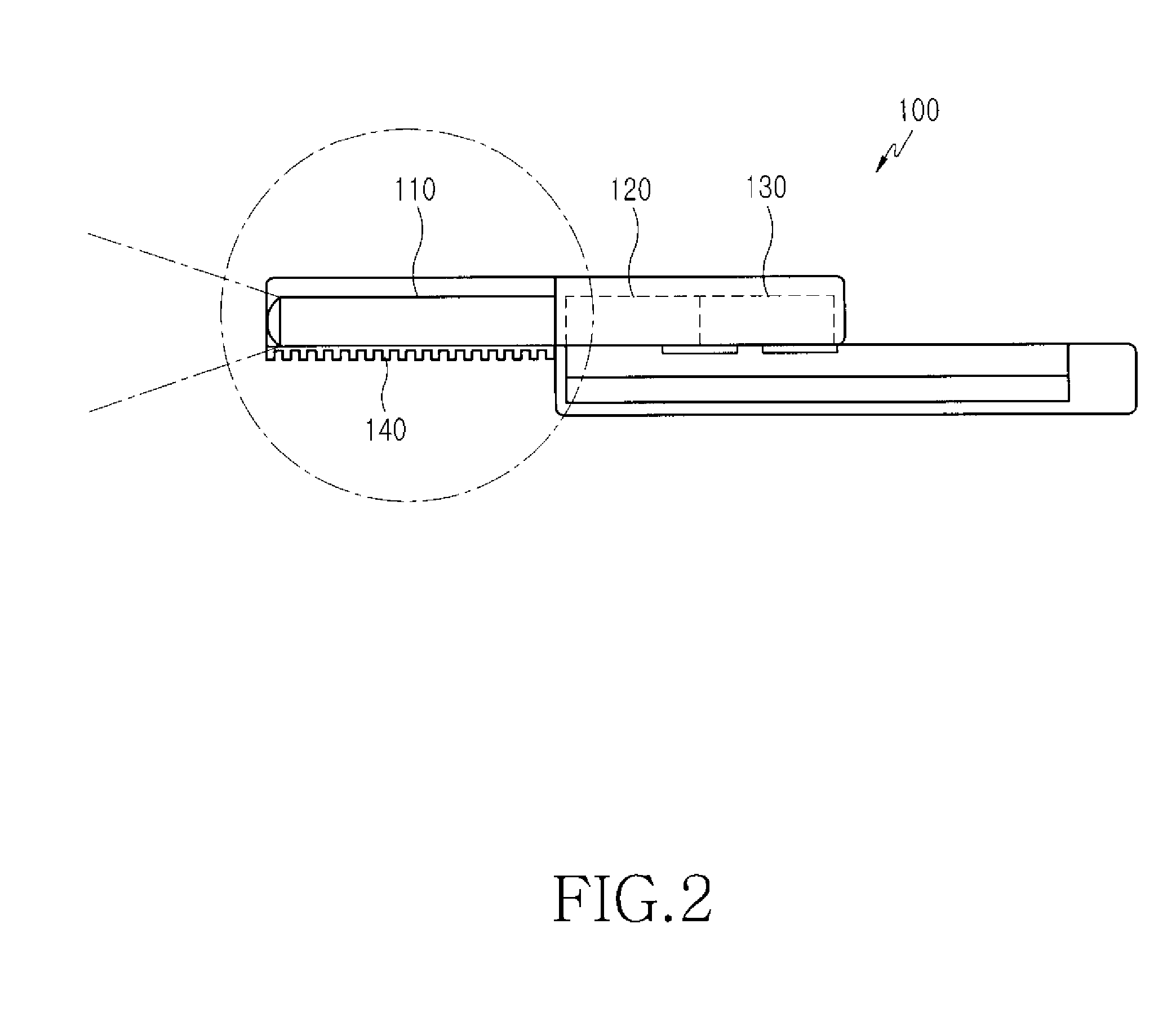
[0031]Hereinafter, certain exemplary embodiments of the present invention will be described with reference to the accompanying drawings. For the purposes of clarity and simplicity, a detailed description of known functions and configurations incorporated herein may be omitted for clarity and conciseness when their inclusion would obscure appreciation of the subject matter of the present invention by a person of ordinary skill in the art. Electric elements having a function of communication and of a light source, such as an LED or an LD, each have different operating temperature ranges. The degrees of degradation in characteristics according to the temperatures are definitely different. Thus, if an electrical part has a hotter heat source than that of an optical part (a projector) upon a comparison of heat generated from those parts, both the parts advantageously have a thermally isolating structure.

[0032]According to the present invention, the heat sources of the optical part and th...


PUM


Abstract

A radiation structure of a mobile communication terminal having a projector which rapidly dissipates heat generated from the projector and other elements built into the terminal. The mobile communication terminal includes a projector implementing an image-projection function, and a projector cover, which is composed of a heat conductive material such that at least one inner surface thereof is brought into close contact with the projector so as to dissipate heat generated from the projector to the outside of the terminal.

Description

CLAIM OF PRIORITY[0001]This application claims priority to an application entitled “Mobile communication terminal having projector” filed in the Korean Intellectual Property Office on Aug. 1, 2007 and assigned Serial No. 2007-77422, the contents of which are hereby incorporated by reference in its entirety.BACKGROUND OF THE INVENTION[0002]1. Field of the Invention[0003]The present invention relates to a mobile communication terminal having a projector, and more particularly to a structure of a mobile communication terminal having a projector which structure enables rapid dissipation of heat generated from the projector and other elements built into the terminal.[0004]2. Description of the Related Art[0005]Recently, with convergence and combination of digital technologies, a projector function (an image-projection function) has been added to a mobile communication terminal. This will enable a user can enjoy contents, such as a moving picture, a still picture, an electronic book, and ...

Claims


Application Information

Patent Timeline
IPC IPC(8): G03B21/16G03B29/00
CPCH04M1/0272G03B21/56H04B1/38
Inventor HEO, DU-CHANGKIM, YONG-KWANJANG, DONG-HOONLEE, JUNG-KEE
Owner SAMSUNG ELECTRONICS CO LTD
Learn More