Zoom lens system

a zoom lens and lens system technology, applied in the field of lenses, can solve the problems of large diameter of the first lens group, long overall length of the zoom lens system, and inability to retra

Inactive Publication Date: 2009-02-05
HOYA CORP
View PDF11 Cites 24 Cited by
  • Summary
  • Abstract
  • Description
  • Claims
  • Application Information

AI Technical Summary

Benefits of technology

[0018]Upon zooming from the short focal length extremity to the long focal length extremity, the distance between the negative first lens group and the positive second lens group decreases, and the distance between the positive second lens group and the positive third lens group increases.

Problems solved by technology

Such a positive-lead type lens system is suitable for reducing the overall length of the lens system; however, the diameter of the first lens group is larger, and is not suitable for the retractable zoom lens camera with a telescopic lens barrel which is arranged to advance and retract.
In Japanese Unexamined Patent Publication No. 2002-277740, zoom lens systems having a zoom ratio in a range of approximately 2.4 through 3.0 are disclosed; however, the zoom lens systems which have a large zoom ratio have a long overall length, so that further miniaturization is not sufficiently achieved.
Japanese Unexamined Patent Publication Nos. 2005-70696 and 2005-70697 disclose relatively smaller optical systems; however, the zoom ratio thereof is approximately 3.0, which is insufficient.
Furthermore, further miniaturization is not sufficiently achieved.
Namely, if attempts are made to achieve an optical system in which aberrations are suitably corrected without increasing the size of the optical system, the number of lens elements has to be increased, and more aspherical lens elements have to be employed, which increases the costs of the optical system.
However, if the zoom ratio is increased up to approximately 4.0, the zoom lens system tends to be longer in the optical axis direction, and the correcting of aberrations becomes difficult.

Method used


Image

  • Zoom lens system
  • Zoom lens system
  • Zoom lens system

Examples


embodiment 1

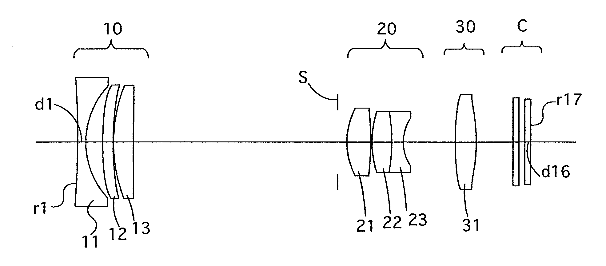
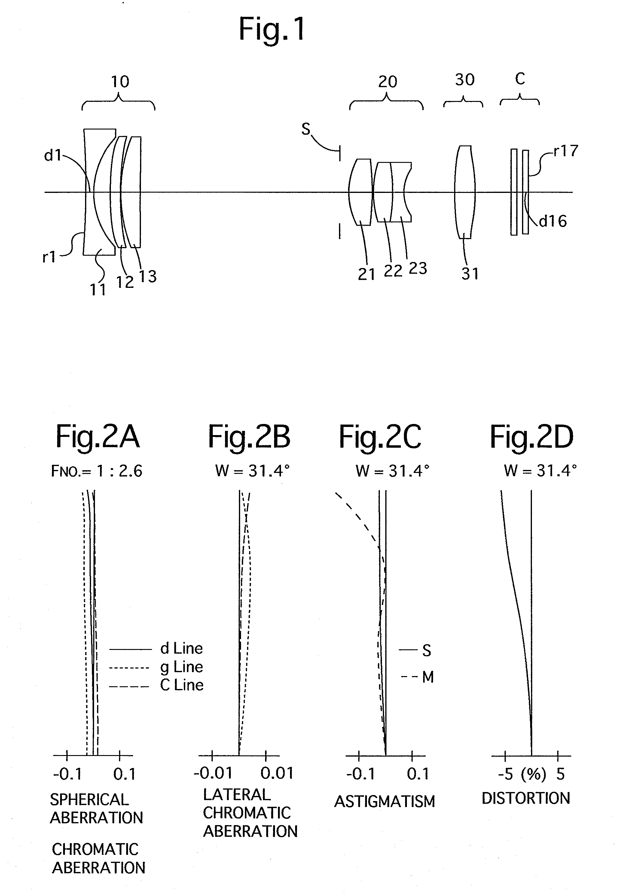
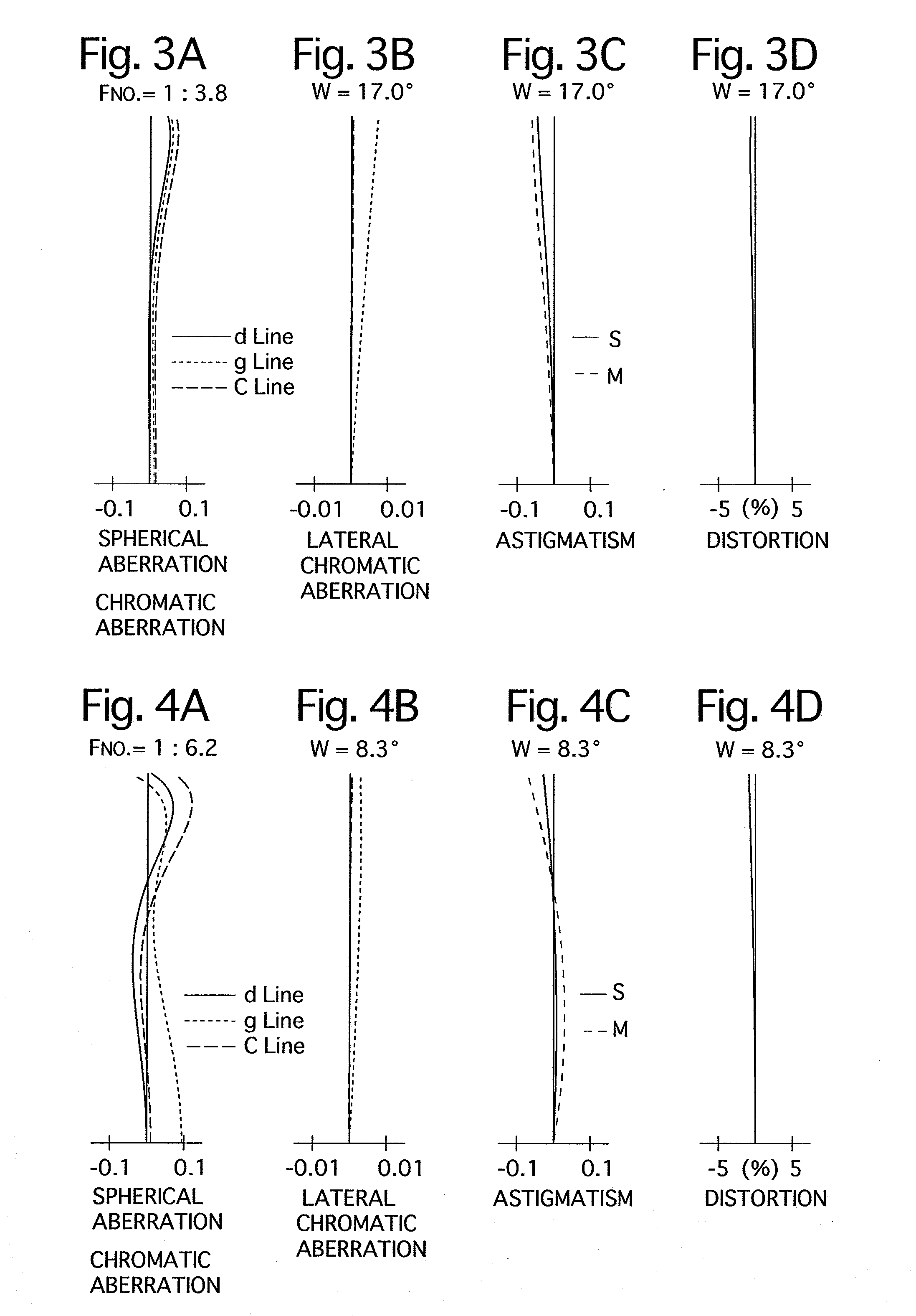
[0140]FIG. 1 shows the lens arrangement of the first embodiment of a zoom lens system according to the present invention. FIGS. 2A through 2D show aberrations occurred in the lens arrangement shown in FIG. 1, when an object at infinity is in an in-focus state at the short focal length extremity. FIGS. 3A through 3D show aberrations occurred in the lens arrangement shown in FIG. 1, when an object at infinity is in an in-focus state at an intermediate focal length. FIGS. 4A through 4D show aberrations occurred in the lens arrangement shown in FIG. 1, when an object at infinity is in an in-focus state at the long focal length extremity.

[0141]Table 1 shows the numerical data of the first embodiment.

[0142]The negative first lens group 10 (surface Nos. 1 through 6) includes a biconcave negative lens element (first lens element) 11, a negative meniscus lens element (second lens element) 12 having the convex surface facing toward the object, and a positive meniscus lens element (third lens ...

embodiment 2

[0147]FIG. 5 shows the lens arrangement of the second embodiment of a zoom lens system according to the present invention. FIGS. 6A through 6D show aberrations occurred in the lens arrangement shown in FIG. 5, when an object at infinity is in an in-focus state at the short focal length extremity. FIGS. 7A through 7D show aberrations occurred in the lens arrangement shown in FIG. 5, when an object at infinity is in an in-focus state at an intermediate focal length. FIGS. 8A through 8D show aberrations occurred in the lens arrangement shown in FIG. 5, when an object at infinity is in an in-focus state at the long focal length extremity.

[0148]Table 2 shows the numerical data of the second embodiment.

[0149]The basic lens arrangement of the second embodiment is the same as that of the first embodiment except that the second lens element 12 of the negative first lens group 10 is a meniscus lens element which has the convex surface facing toward the object, has a weak positive refractive p...

embodiment 3

[0151]FIG. 9 shows the lens arrangement of the third embodiment of a zoom lens system according to the present invention. FIGS. 10A through 10D show aberrations occurred in the lens arrangement shown in FIG. 9, when an object at infinity is in an in-focus state at the short focal length extremity. FIGS. 11A through 11D show aberrations occurred in the lens arrangement shown in FIG. 9, when an object at infinity is in an in-focus state at an intermediate focal length. FIGS. 12A through 12D show aberrations occurred in the lens arrangement shown in FIG. 9, when an object at infinity is in an in-focus state at the long focal length extremity.

[0152]Table 3 shows the numerical data of the third embodiment.

[0153]The basic lens arrangement of the third embodiment is the same as that of the first embodiment except the fifth lens element 22 and the sixth lens element 23 which constitute the cemented lens of the positive second lens group 20. More specifically, the fifth lens element 22 is a ...


PUM


Abstract

A zoom lens system includes a negative first lens group, a positive second lens group, and a positive third lens group, in this order from the object.
Upon zooming from the short focal length extremity to the long focal length extremity, the distance between the negative first lens group and the positive second lens group decreases, and the distance between the positive second lens group and the positive third lens group increases.
The negative first lens group includes a negative first lens element, a positive or negative lens element having a weaker refractive power, and a positive third lens element, in this order from the object.
The zoom lens system satisfied the following condition:
−0.25<f1/fp<0.25(f1<0)   (1)
    • wherein
    • f1 designates the focal length of the negative first lens group; and
    • fp designates the focal length of the positive second lens element.

Description

BACKGROUND OF THE INVENTION[0001]1. Field of the Invention[0002]The present invention relates to a lens system, which is inexpensive, has adequate telecentricity and a zoom ratio of approximately 4.0, to be used in a small and light-weight digital camera, etc.[0003]2. Description of the Prior Art[0004]In recent years, further miniaturization of digital compact cameras due to further miniaturization of electronic components have progressed, and further miniaturization of the photographing optical system is also in demand.[0005]Furthermore, due to higher pixelization of imaging devices, photographing optical systems are required to have higher resolution.[0006]In order to prevent shading and color shift, excellent telecentricity, by which light emitting from the rearmost lens surface is orthogonally incident on the imaging surface, is required in the photographing optical system of a digital camera.[0007]A negative-lead type lens system having a zoom ratio of approximately 3 is often ...

Claims


Application Information

Patent Timeline
Patent Type & Authority Applications(United States)
IPC IPC(8): G02B15/177G02B15/20
CPCG02B15/177G02B13/22G02B15/143507
Inventor EGUCHI, MASARU
Owner HOYA CORP
Why Eureka
Try Eureka