System and Method for Eliminating Feedback and Noise In a Hearing Device

a hearing aid and acoustic feedback technology, applied in the field of system and method for eliminating acoustic feedback and noise in the hearing aid, can solve the problems of audible distortion of the original input signal, degrading the sound quality of the user of the hearing aid, and problems such as and achieve the effect of removing the noise in the incoming signal

Active Publication Date: 2009-02-05
OTICON
View PDF0 Cites 44 Cited by
  • Summary
  • Abstract
  • Description
  • Claims
  • Application Information

AI Technical Summary

Benefits of technology

[0012]A particular advantage of the present invention is the provision of means for re-synthesizing all or parts of an incoming signal and therefore the incoming signal may be re-established before communicated to a user of the hearing device.
[0013]A particular feature of the present invention is the provision of a noise detection means for detecting noise and removing the noise in the incoming signal.
[0014]The above objects, advantage and feature together with numerous other objects, advantages and features, which will become evident from below detailed description, are obtained according to a first aspect of the present invention by a system for synthesizing an audio input signal of a hearing device and comprising a microphone unit adapted to convert said audio input signal to an electric signal, a filter unit adapted to remove a selected frequency band of said electric signal and pass a filtered signal, a synthesizer unit adapted to synthesize said selected frequency band of said electric signal based on said filtered signal thereby generating a synthesized signal, a combiner unit adapted to combine said filtered signal and said synthesized signal thereby generating a combined signal, and an output unit adapted to convert said combined signal to an audio output signal.
[0015]The term “hearing device” is in this context to be construed as a hearing aid, a headset, a head-phone and similar microphone-amplifier-speaker devices.
[0016]The term “process” is in this context to be construed as any signal processing aiming to enhance the input signal to provide an output signal according to individual user's needs. In particular, this may involve constant gain or input level dependent gain (amplitude compression) in any frequency bands within the signal. The term “amplitude compression” (or just “compression”) is in this context to be construed as performing level dependent gain. In particular, in hearing impairment with cochlear origin the dynamic range between the weakest detectable sounds (hearing thresholds) and the loudest sounds (uncomfortable loudness levels) is typically less than for normal hearing persons. Usually this narrowing of the dynamic range is also frequency dependent. Furthermore, the hearing thresholds are more affected by hearing impairment than the uncomfortable loudness levels. Therefore, there can be a need to amplify weak input sounds more than loud sounds, hence to “compress” the input level dynamic range to the output dynamic range.
[0017]By removing a selected frequency band in the incoming electric signal acoustic feedback between the output unit and the microphone or noise in a particularly frequency band is effectively eliminated. The synthesized signal may be acoustically fed back to the microphone, but since it is removed from the electric signal by the filter unit it is irrelevant. One could say that the selected frequency band is muted in the hearing device and synthesized restoring the original audio input.

Problems solved by technology

Acoustic feedback and external noise in hearing aids are problems, which have been compensated in a number of ways in the prior art.
Even though this system reduces the effects of acoustic feedback, filtering of the incoming signal to remove acoustic feedback distorts the acoustic sounds to be presented to the user of the hearing aid, since the feedback-inhibiting filter removes some of the original signal in the process, which is not restored.
Erroneous estimations of the acoustic feedback introduce audible distortions to the original input signal due to the subtraction.
For example music with tonal inputs may cause the feedback cancellation system to try to cancel the tonal parts of the music thus degrading sound quality for the user of a hearing aid.
However, this may introduce a distortion of the original speech signal in presence of noise, since the noise-dominated channels / bands are attenuated if they are classified as noisy.

Method used


Image

  • System and Method for Eliminating Feedback and Noise In a Hearing Device
  • System and Method for Eliminating Feedback and Noise In a Hearing Device
  • System and Method for Eliminating Feedback and Noise In a Hearing Device

Examples


first embodiment

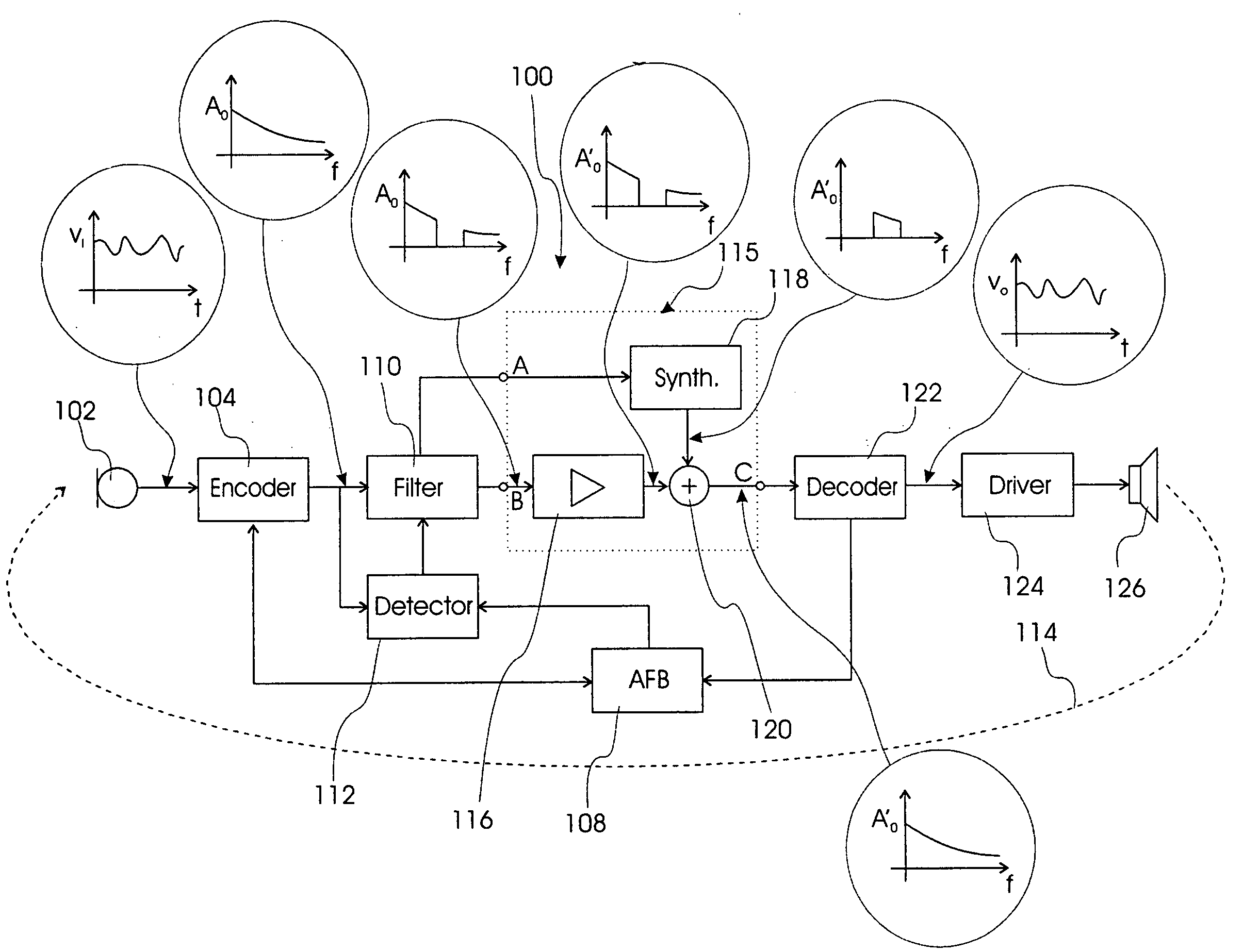
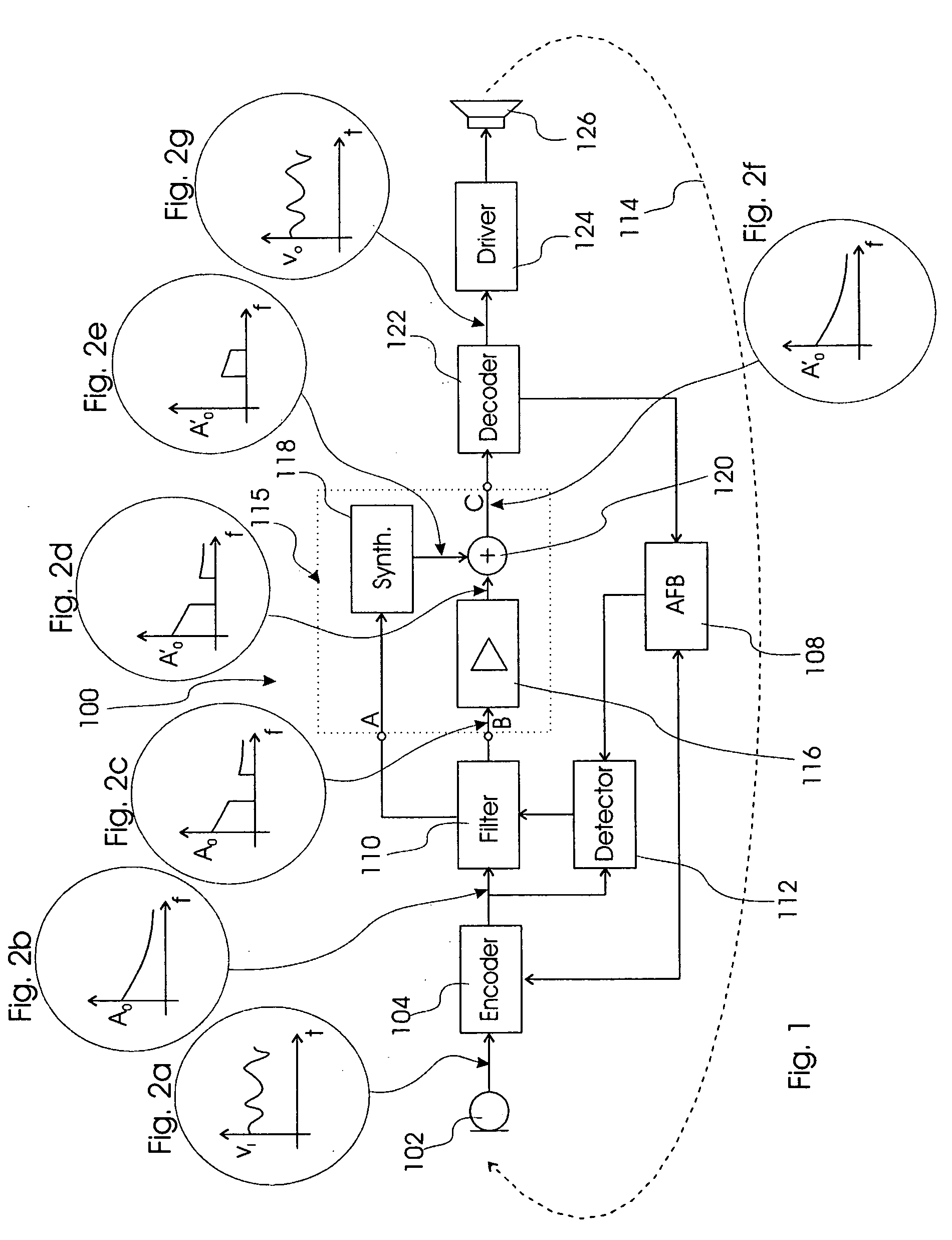
[0050]FIG. 1 shows a system for synthesizing an audio input signal according to the present invention, which system is designated in entirety by reference numeral 100. The system 100 comprises a microphone 102 converting a sound pressure into a time varying electric signal, for example such as shown in FIG. 2a. The description relating to FIGS. 2a through 2f is incorporated in the description relating to FIG. 1.

[0051]Obviously, the system 100 may comprise any number of microphones such as two or more used for determining a directionality function. However, the following description and figures show only one microphone 102 for simplicity.

[0052]The sound pressure forms an audio input signal, which is converted by the microphone 102 to the electric signal and communicated to an encoder 104. The term “encoder” is in this context be construed as a transforming, encoding and / or converting element.

[0053]The encoder 104 according to the first embodiment of the present invention comprises a ...

second embodiment

[0072]FIG. 4 shows a system for synthesizing an audio input signal according to the present invention, which is designated in entirety by reference numeral 400. Similar elements and units described with reference to FIGS. 1, 3a and 3b are designated by identical reference numerals.

[0073]The system 400 comprises a microphone 102 generating an electric signal to a processing unit 402, which processes the electric signal according to a setting stored in a memory 404 communicating with the processing unit 402. The processing unit 402 generates a processed signal, which is forwarded to a driver 124 driving a speaker 126 to generate an audio output signal.

[0074]The processing unit 402 comprises an encoder 104, an anti-feedback unit 108, a filter unit 110 and a detector 112, and a signal processing unit 115 operating as described above with reference to FIGS. 1, 3a or 3b. The detector 112 controls the filter unit 110 and forwards frequency bandwidth information to a controller processor 40...

third embodiment

[0080]FIG. 5 shows a system according to the present invention, which is designated in entirety by reference numeral 500. Similar elements and units described with reference to FIGS. 1, 3a, 3b, and 4 are designated by identical reference numerals.

[0081]The system 500 operates as described above with reference to FIG. 4, however, the system 500 comprises a processing unit 502, wherein instead of having an anti-feedback unit for generating an anti-feedback signal or feedback signal the processing unit 502 comprises a detector 112 with an howl element determining from the signal in the encoder 104 whether acoustic feedback is present in the forward signal path. Hence the system 500 entirely utilises the signal processing unit 115 for eliminating acoustic feedback; that is by removal and synthesis of a frequency bandwidth.

[0082]FIG. 6a shows a graph of a first example of a transposition of source frequency bands 2.0 to 2.5; 2.5 to 3.0; 3.0 to 3.5; and 3.5 to 4.0 kHz to four resultant fr...


PUM


Abstract

This invention relates to a system (100) and method for synthesizing an audio input signal of a hearing device. The system (100) comprises a microphone unit (102) for converting the audio input signal to an electric signal, a filter unit (110) for removing a selected frequency band of the electric signal and pass a filtered signal, a synthesizer unit (118) for synthesizing the selected frequency band of the electric signal based on the filtered signal thereby generating a synthesized signal, a combiner unit (120) for combining the filtered signal and the synthesized signal so as to generate a combined signal, and finally an output unit (122, 124, 126) for converting the combined signal to an audio output signal.

Description

FIELD OF INVENTION[0001]This invention relates to a system and method for eliminating acoustical feedback and noise in a hearing device such as a hearing aid, headset or head-phone. In particular, this invention relates to a hearing aid such as a behind-the-ear (BTE), in-the-ear (ITE) or completely-in-canal (CIC) hearing aid, wherein undesirable acoustical feedback from the speaker to the microphone is eliminated together with noise.BACKGROUND OF INVENTION[0002]Acoustic feedback and external noise in hearing aids are problems, which have been compensated in a number of ways in the prior art.[0003]In regards to acoustical feedback several known methods are used for reducing the negative effects introduced by acoustic feedback in a hearing aid, this includes notch filtering, frequency compression, modification of the phase response, and feedback cancellation, such as disclosed in M. Sc. Thesis entitled “Digital suppression of acoustic feedback in hearing aids” written by Best L. C. an...

Claims


Application Information

Patent Timeline
Patent Type & Authority Applications(United States)
IPC IPC(8): H04R25/00
CPCH04R25/453
Inventor LUNNER, THOMAS
Owner OTICON
Why Eureka
Try Eureka