Photonic crystal ribbon-beam traveling wave amplifier

Inactive Publication Date: 2005-03-24
MASSACHUSETTS INST OF TECH
View PDF13 Cites 5 Cited by
  • Summary
  • Abstract
  • Description
  • Claims
  • Application Information

AI Technical Summary

Benefits of technology

According to another aspect of the invention, there is provided a method of forming a RF amplifier. The method includes forming RF input section for receiving a RF input signal. Also, the method includes forming al least one photonic crystal for operational control if necessary. An electron ribbon beam is formed that in

Problems solved by technology

For the RF power part of a wireless base station, the operating cost is comparable to the capital cost, because of the low operating efficiencies and heat removal.
Conventional helix traveling wave tubes (TWTs), which are not employed in any existing wireless base stations, cannot meet the ultra-low-cost requirement set by any potential third-generation wireless infrastructure provider.

Method used


Image

  • Photonic crystal ribbon-beam traveling wave amplifier
  • Photonic crystal ribbon-beam traveling wave amplifier
  • Photonic crystal ribbon-beam traveling wave amplifier

Examples


Embodiment Construction

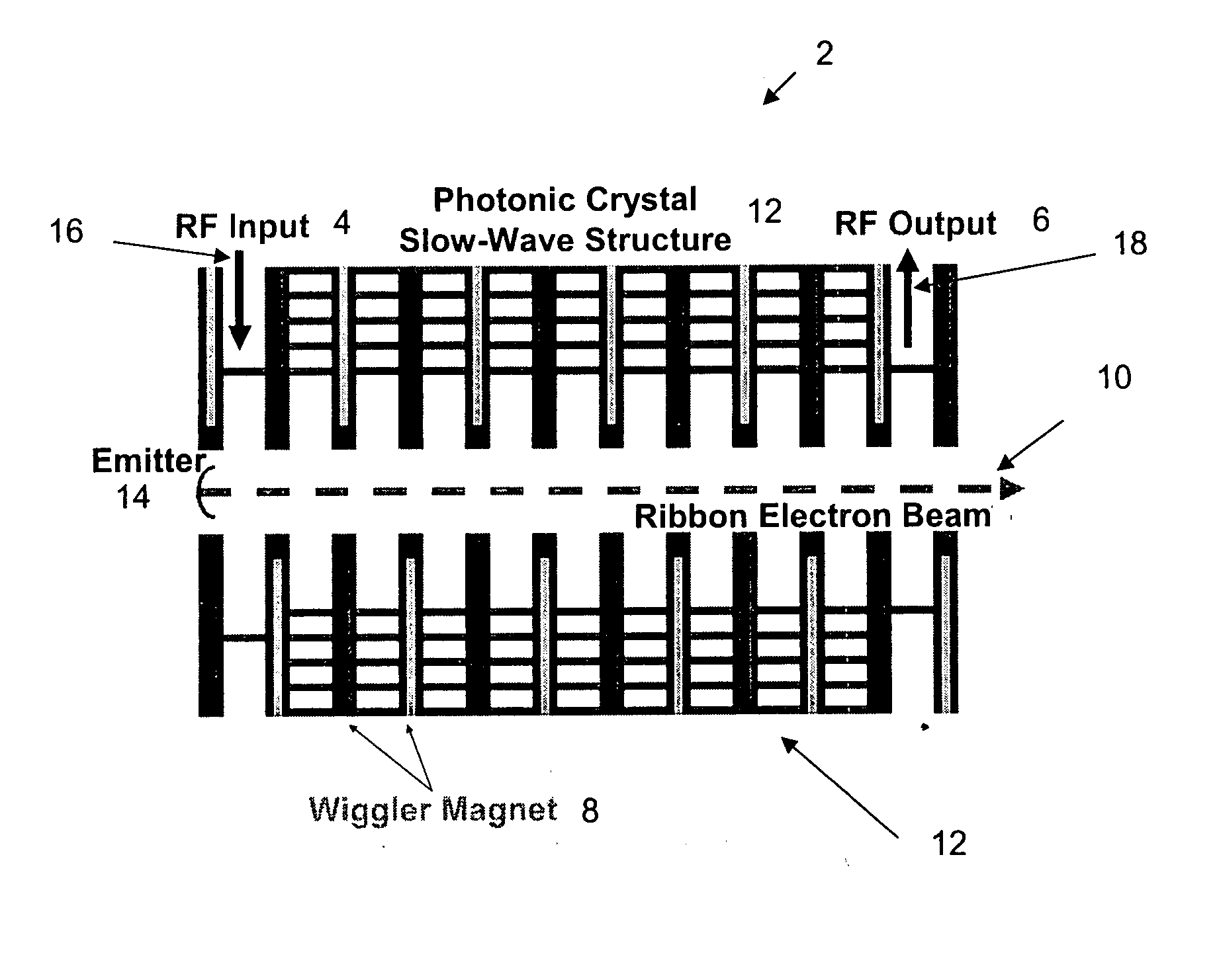
The invention is a novel amplifier that employs two emerging technologies, namely, photonic crystals and low-density ribbon electron beams, in otherwise a conventional vacuum tube millimeter wave amplifier.

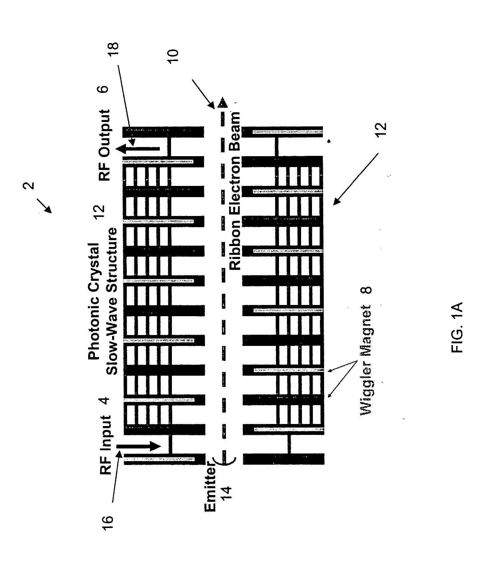
FIGS. 1A-1B shows a schematic diagram of a photonic crystal ribbon-beam traveling wave amplifier (PCRB TWA) 2 in accordance with the invention. FIG. 1A shows a double sided PCRB TWA 2 that includes a ribbon electron beam 10 propagating in the z-direction from the emitter 14 and extending out, wiggler magnets 8 for beam focusing, a photonic crystal (PC) slow-wave structure 12 with metallic or dielectric rods and plates, and RF input 4 and output 6 sections. As the electron beam 10 interacts with the RF input 4 supported by slow-wave structure 12, the kinetic energy of the electron beam is transferred to the RF fields, amplifying the RF signal 16. The amplified RF signal 18 exits the amplifier at the RF output 6, and the spent electron beam is collected down stream.
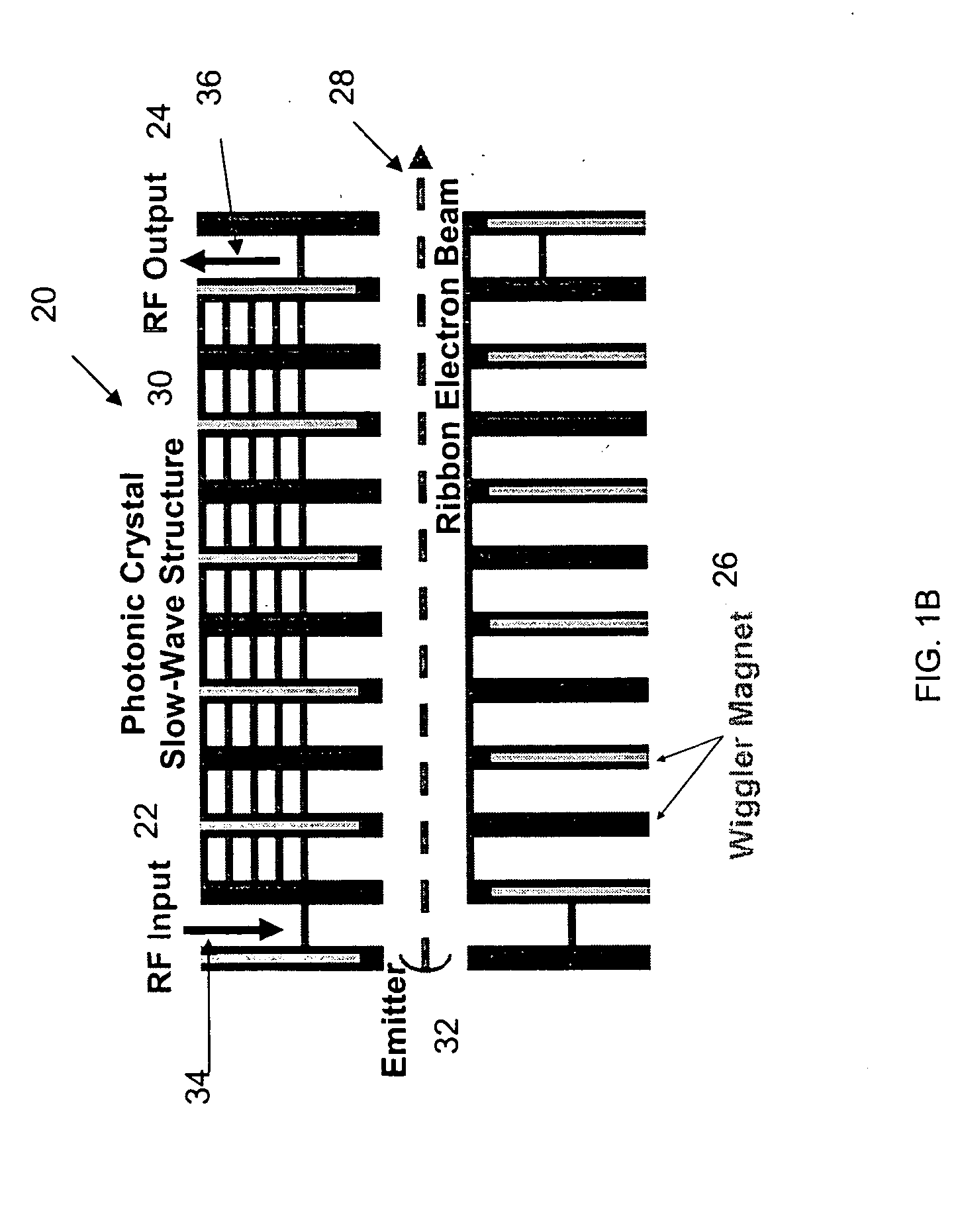
FIG. 1B shows ...


PUM


Abstract

A RF amplifier includes a RF input section for receiving a RF input signal. At least one single-sided slow-wave structure is associated with the RF interaction section. An electron ribbon beam that interacts with the RF input supported by the at least one single-sided slow-wave structure so that the kinetic energy of the electron beam is transferred to the RF fields of the RF input signal, thus amplifying the RF input signal. A RF output section outputs the amplified RF input signal.

Description

BACKGROUND OF THE INVENTION The invention relates to the field of optical communication, and in particular to a photonic crystal ribbon-beam traveling wave amplifier. The third-generation (3G) wireless communication standards call for hardware-based upgrade to the second-generation (2G) Global Systems for Mobile Communications using Wideband Code Division Multiple Access (W-CDMA) and Universal Mobile Telephone System (UMTS) as well as software-based upgrade to 2G Code Division Multiple Access (CDMA). The 3G wireless communications require amplifiers operating frequencies that are 1.12 to 3 times that of present frequencies, which are in the range from 900 MHz to 1700 MHz. In general, the bandwidth of a transmitter, which is the most important figure of merit, increases with the central frequency of the amplifier. However, the number of transmitting towers must increase as the square of the central frequency, while keeping the power of the transmitting tower at a constant. This is...

Claims


Application Information

Patent Timeline
IPC IPC(8): H01J23/24H01J23/54H01J25/34H01J25/38
CPCH01J23/24H01J25/44H01J25/38
Inventor CHEN, CHIPINGQIAN, BAO-LIANGTEMKIN, RICHARD J.
Owner MASSACHUSETTS INST OF TECH
Why Eureka
Try Eureka