Method and apparatus for inspecting components

a technology for components and inspection methods, applied in the field of components inspection, can solve the problems of difficult operator selection of signals, reduced efficiency, and reduced accuracy, and achieve the effect of reducing the quantity of prospective signals contained

Active Publication Date: 2009-02-05
GENERAL ELECTRIC CO
View PDF16 Cites 20 Cited by
  • Summary
  • Abstract
  • Description
  • Claims
  • Application Information

AI Technical Summary

Benefits of technology

[0006]In one aspect, a method for inspecting a component is provided. The method includes generating an image of the component, generating a signal indication mask, and generating a noise mask using a signal within the signal indication mask. The noise mask facilitates reducing a quantity of prospective signals contained in the signal indication mask. The method further includes utilizing the signal indication mask and the generated noise mask to calculate the signal-to-noise ratio of at least one potential flaw indication that may be present in the image.
[0007]In another aspect, a signal detection system is provided. The signal detection system includes a probe and a processor coupled to the probe. The processor is programmed to generate an image of the component using the probe, generate a signal indication mask, and generate a noise mask based on the signal indication mask. The noise mask facilitates reducing a quantity of prospective signals contained in the signal indication mask. The processor is further programmed to calculate the signal-to-noise ratio of at least one potential flaw indication that may be present in the image using the signal indication mask and the generated noise mask.

Problems solved by technology

While this technique is acceptable for images having a homogenous background noise, this technique is less effective when the image includes variable background noise which obscures the homogenous noise thus making the selection of the signal by the operator both difficult and subject to operator interpretation.

Method used


Image

  • Method and apparatus for inspecting components
  • Method and apparatus for inspecting components
  • Method and apparatus for inspecting components

Examples


Embodiment Construction

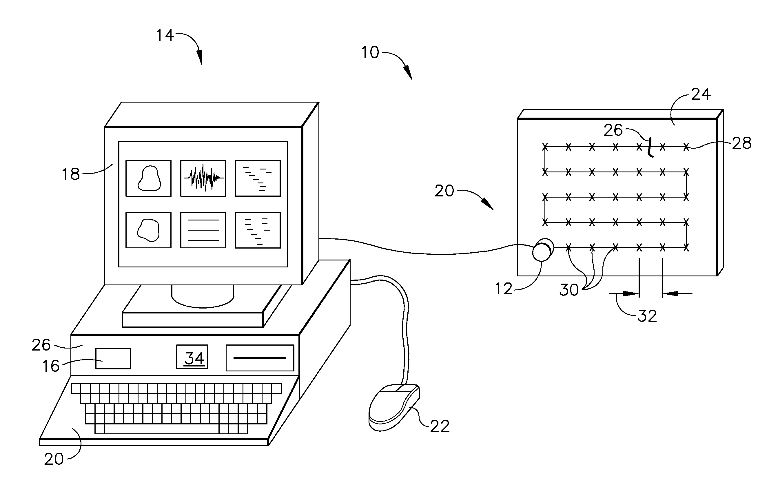
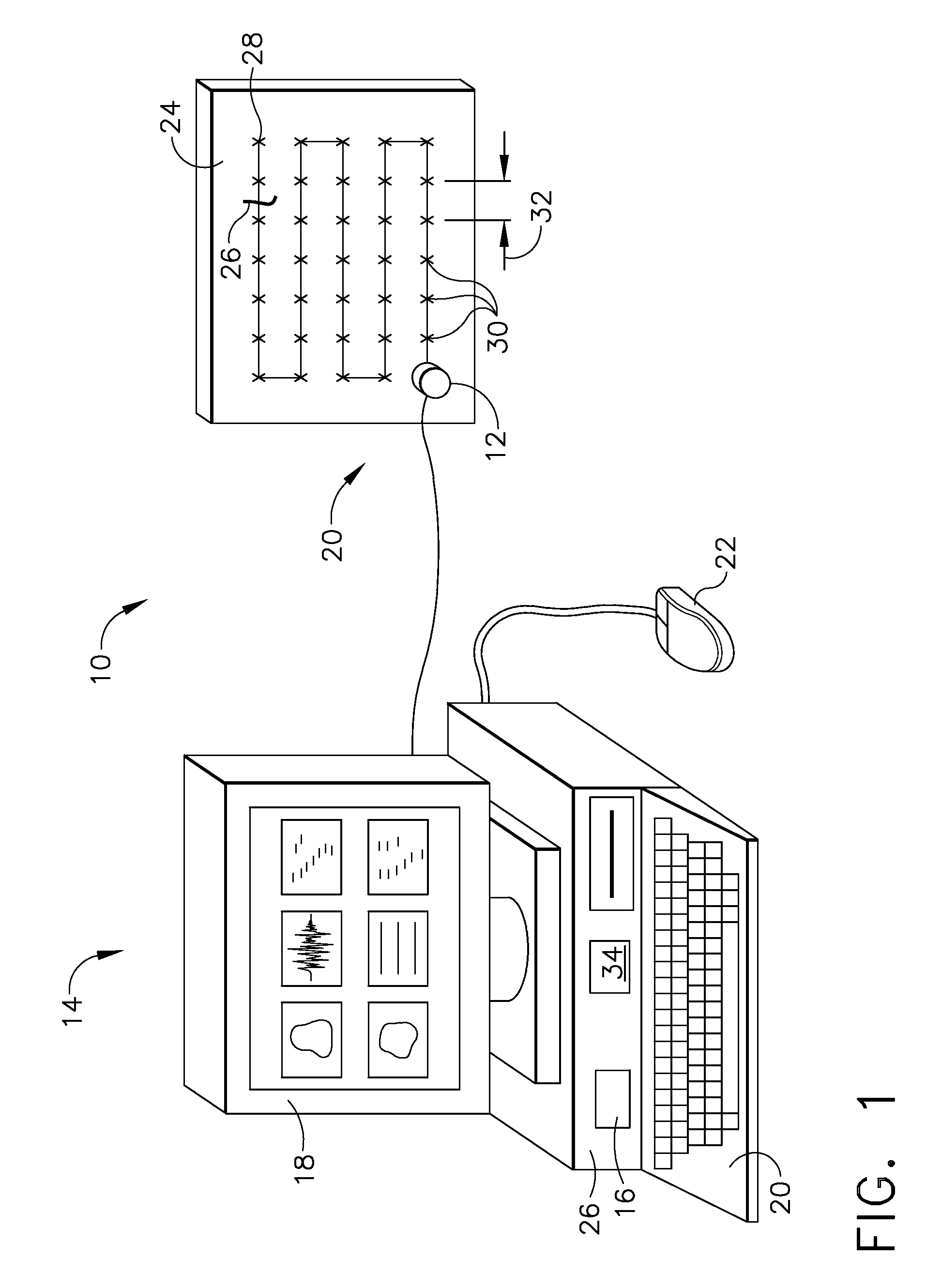
[0013]As used herein, the term “component” may include any component that may be imaged such that an image with variable noise and / or a variable background structure is generated. For example, in one embodiment, a component is any signal of interest that may be imaged. Another example of a component is a component that is configured to be coupled within a gas turbine engine and that may be coated with a wear-resistant coating, for example a turbine shroud support. A turbine shroud support is intended as exemplary only, and thus is not intended to limit in any way the definition and / or meaning of the term “component”. Furthermore, although the invention is described herein in association with a gas turbine engine, and more specifically in association with a rotor for a gas turbine engine, it should be understood that the present invention is applicable to other turbine engine stationary components and rotatable components, power system components, pipe line components, and / or any oth...


PUM


Abstract

A method for inspecting a component is provided. The method includes generating an image of the component, generating a signal indication mask, and generating a noise mask using a signal within the signal indication mask. The noise mask facilitates reducing a quantity of prospective signals contained in the signal indication mask. The method further includes utilizing the signal indication mask and the generated noise mask to calculate the signal-to-noise ratio of at least one potential flaw indication that may be present in the image.

Description

BACKGROUND OF THE INVENTION[0001]This invention relates generally to the inspection of components and, more particularly, to a method and apparatus for performing nondestructive testing of fabricated components.[0002]Where nondestructive evaluation of a workpiece or component is required, ultrasonic inspection techniques are used in many applications. One application of such ultrasonic inspection is in the inspection of gas turbine engine components such as rotors and blades, for example. Such components are typically formed from forging or casting a material with desired metallurgical properties. In the production of aerospace rotating components, the entire volume of the finished component is required to be inspected ultrasonically.[0003]More specifically, there are many inspection or sensing applications where data are collected and stored for analysis. Certain types of applications are designed to detect signals from the ultrasonic probes or sensors in conditions where the backg...

Claims


Application Information

Patent Timeline
IPC IPC(8): G06K9/00
CPCG01N29/0645G01N29/069G01N29/32G01N29/4463G01N2291/0289G06T2207/30164G01N2291/2693G06T7/001G06T2207/10132G06T2207/20021G06T2207/30116G01N2291/101
Inventor FERRO, ANDREW FRANKHOWARD, PATRICK JOSEPH
Owner GENERAL ELECTRIC CO
Why Eureka
Try Eureka