
Developing method, developing apparatus and storage medium

a technology of developing apparatus and storage medium, which is applied in the direction of printing, photosensitive materials, instruments, etc., can solve the problems of requiring a greater amount of developing solution, and reducing the development time and/or developing solution cannot be applied adequately, so as to achieve the effect of substantially avoiding or suppressing the supply of developing solution on the substra

Inactive Publication Date: 2009-02-05
TOKYO ELECTRON LTD
View PDF3 Cites 12 Cited by
  • Summary
  • Abstract
  • Description
  • Claims
  • Application Information

AI Technical Summary

Benefits of technology

[0014]One aspect of the present invention is a developing method, comprising the steps of: holding a substrate, horizontally, on a substrate holding part, the substrate having been coated with a resist and then subjected to an exposure process; supplying a developing solution from a first developing solution nozzle onto either one of a central portion or peripheral portion of a surface of the substrate, so as to form a ribbon-like region on the surface of the substrate, while rotating the substrate about a vertical axis via the substrate holding part, wherein one end of the ribbon-like region is oriented toward the central portion of the substrate; shifting a position of the ribbon-like region, in which the developing solution is supplied, from either one of the central portion or peripheral portion of the surface of the substrate toward the other of the central portion or peripheral portion thereof, while orienting the one end of the ribbon-like region of the developing solution toward the central portion of the substrate, thereby forming a liquid film of the developing solution on the surface of the substrate; and supplying the developing solution from a second developing solution nozzle, so as to form a circular region on the central portion of the substrate or form a ribbon-like region shorter in length than the ribbon-like region of the developing solution supplied from the first developing nozzle, in order to prevent the liquid film of the developing solution from being dried up, while rotating the substrate about the vertical axis via the substrate holding part, thereby spreading the developing solution toward the peripheral portion of the substrate by centrifugal force.
[0015]Another aspect of the present invention is a developing apparatus, comprising: a substrate holding part adapted for horizontally holding a substrate having been coated with a resist and then subjected to an exposure process; a rotation driving mechanism adapted for rotating the substrate holding part holding the substrate, about a vertical axis; a first developing solution nozzle adapted for supplying a developing solution onto a surface of the substrate, so as to form a ribbon-like region of the developing solution extending in a direction from a central portion toward a peripheral portion of the substrate, while one end of the ribbon-like region is oriented toward the central portion of the substrate, thereby forming a liquid film of the developing solution; a driving mechanism adapted for moving the first developing solution nozzle, so as to shift a position of the ribbon-like region, in which the developing solution is supplied, from either one of the central portion or peripheral portion of the surface of the substrate toward the other of the central portion or peripheral portion thereof, while the one end of the ribbon-like region of the developing solution is oriented toward the central portion of the substrate; and a second developing solution nozzle adapted for supplying the developing solution, so as to form a circular region on the central portion of the substrate or form a ribbon-like region shorter in length than the ribbon-like region of the developing solution supplied from the first developing nozzle, in order to prevent the liquid film of the developing solution from being dried up.
[0017]Still another aspect of the present invention is a storage medium for storing therein a computer program for driving a computer to perform a developing method, the developing method comprising the steps of: holding a substrate, horizontally, on a substrate holding part, the substrate having been coated with a resist and then subjected to an exposure process; supplying a developing solution from a first developing solution nozzle onto either one of a central portion or peripheral portion of a surface of the substrate, so as to form a ribbon-like region on the surface of the substrate, while rotating the substrate about a vertical axis via the substrate holding part, wherein one end of the ribbon-like region is oriented toward the central portion of the substrate; shifting a position of the ribbon-like region, in which the developing solution is supplied, from either one of the central portion or peripheral portion of the surface of the substrate toward the other of the central portion or peripheral portion thereof, while keeping orienting the one end of the ribbon-like region of the developing solution toward the central portion, thereby forming a liquid film of the developing solution on the surface of the substrate; and supplying the developing solution from a second developing solution nozzle, so as to form a circular region on the central portion of the substrate or form a ribbon-like region shorter in length than the ribbon-like region of the developing solution supplied from the first developing nozzle, in order to prevent the liquid film of the developing solution from being dried up, while rotating the substrate about the vertical axis via the substrate holding part, thereby spreading the developing solution toward the peripheral portion of the substrate by centrifugal force.
[0018]According to this invention, the step of forming the liquid film of the developing solution on the substrate is performed by using the first developing solution nozzle adapted for supplying the developing solution onto the surface of the substrate, such that the supplied developing solution will be formed into the ribbon-like region, with one end of the ribbon-like region being oriented toward the central portion of the substrate; and the step of further supplying the developing solution, in order to prevent the drying up of the liquid film of the developing solution, is performed by using the second developing solution nozzle adapted for supplying the developing solution onto the substrate, such that the further supplied developing solution will be formed into the circular shape or ribbon-like region shorter in length than the ribbon-like region of the developing solution supplied from the first developing solution nozzle. By selecting the developing solution nozzles, in this manner, corresponding to the step required, unstable supply of the developing solution onto the substrate can be substantially avoided or suppressed, as compared with the case of supplying the developing solution onto the substrate by using, for example, only the first developing solution nozzle while changing a discharging amount from the nozzle. Since the amount of supplying the developing solution onto the substrate can be controlled, corresponding to the shape formed from the developing solution discharged from each nozzle, the amount of the developing solution to be supplied onto the substrate can be significantly saved.

Problems solved by technology

However, such a paddling-type developing method requires a greater amount of the developing solution.
However, when attempting to suppress occurrence of a developing defect or defect in a developed state and ensure uniformity of a preferred CD (i.e., a width of lines in the resist pattern), some resist materials may substantially restrict a process margin.
Thus, in some cases, such a developing process, as described above, that aims at significant reduction of the developing time and / or developing solution cannot be applied adequately.
Accordingly, substantial reduction or saving of the developing time and developing solution is still a challenge to be studied in performing the developing process.
Nevertheless, if the supply of the developing solution 14 is continued, in the same amount that is used for forming the liquid film 15, the attempt of reducing the amount of the developing solution 14 used would not be achieved enough.
Namely, with such a design, the developing solution can be supplied, stably, in a ribbon-like state, onto the wafer W. Therefore, if the developing solution is supplied to the developing solution nozzle 13, in a smaller amount than the predetermined amount, the discharge of the developing solution 14 from the discharging hole 12 should be unstable, thus making it difficult to perform a normal and adequate developing process, leading to occurrence of the developing defect and / or significant dispersion in the resist pattern.
Accordingly, while the Patent Document 1 describes one aspect of the method for supplying the developing solution several times onto the substrate, it does not teach any measure for addressing the above problem.

Method used


Image

  • Developing method, developing apparatus and storage medium
  • Developing method, developing apparatus and storage medium
  • Developing method, developing apparatus and storage medium

Examples


examples

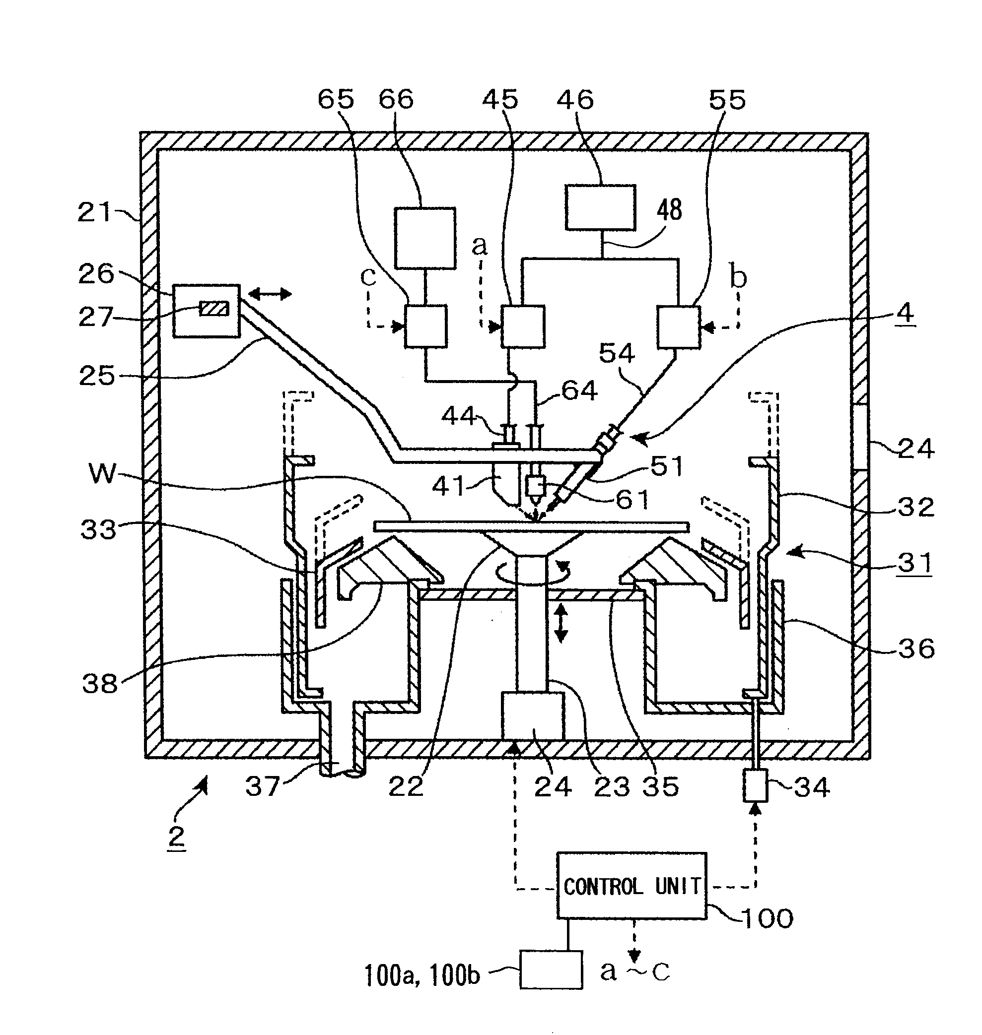
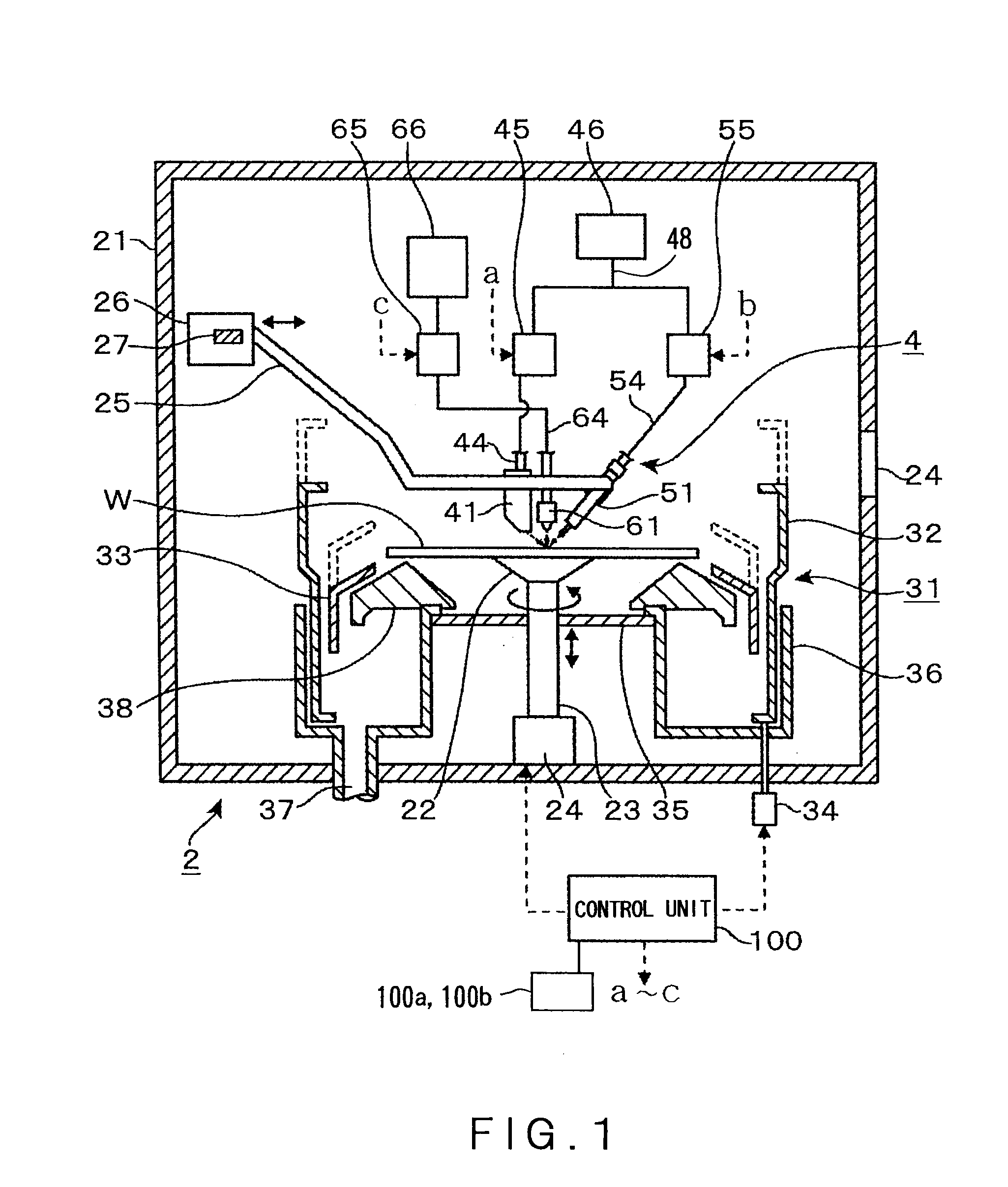
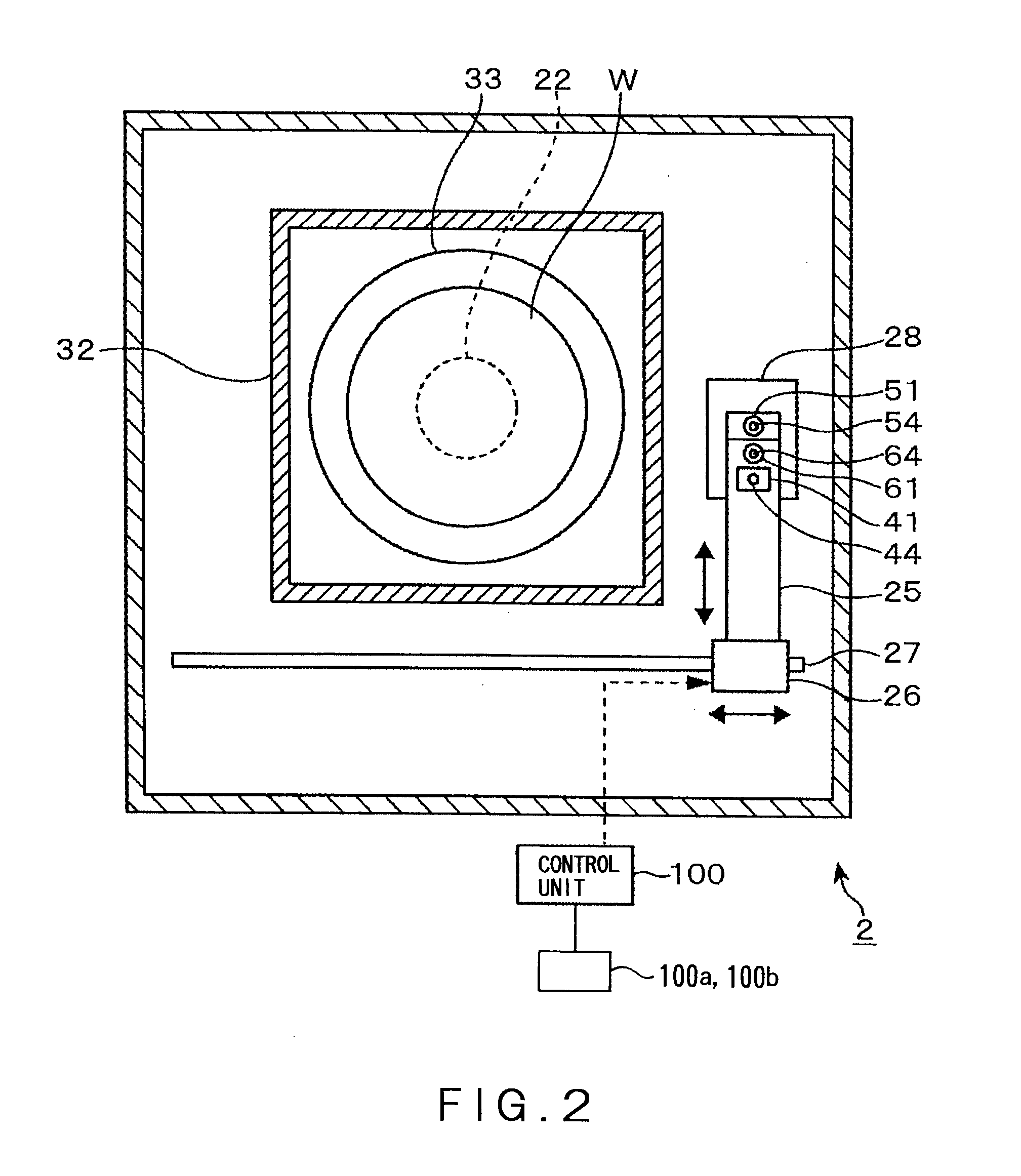
[0033]Now, a developing apparatus 2 according to the present invention will be described with reference to FIGS. 1 and 2. The developing apparatus 2 includes a housing 21, in which a spin chuck 22 is provided. The spin chuck is used as a substrate holding part adapted for chucking and holding, for example, a central portion of a rear face of the wafer W in a horizontal position. The spin chuck 22 is connected with a driving mechanism 24 adapted for rotating the spin chuck 22 about a rotation axis 23. The rotation axis 23 of the spin chuck 22 is positioned such that the center of the wafer W is located thereon. The spin chuck 22 is configured such that it can be rotated about a vertical axis as well as raised and lowered along a vertical axis, by the driving mechanism 24, while holding the wafer W thereon. The rotational speed of the spin chuck 22 during the developing process is controlled each time the driving mechanism 24 receives a control signal from a control unit.

[0034]A cup-l...


PUM


Abstract

The present invention provides a method of supplying a developing solution, stably, onto a substrate, upon providing a developing process to the substrate which has been coated with a resist and subjected to an exposure process. In this method, the developing solution is supplied onto the substrate from a first developing solution nozzle, so as to form a ribbon-like region on the surface of the substrate, while rotating the substrate about a vertical axis via a substrate holding part, wherein one end of the ribbon-like region is oriented toward a central portion of the substrate. At this time, by shifting a position of the ribbon-like region in which the developing solution is supplied, a liquid film of the developing solution can be formed on the surface of the substrate. Subsequently, in order to prevent the liquid film of the developing solution from being dried up, the developing solution is supplied from a second developing solution nozzle, so as to form a circular region on the central portion of the substrate or form a ribbon-like region shorter in length than the ribbon-like region of the developing solution supplied from the first developing nozzle. Simultaneously, the substrate is rotated about the vertical axis via the substrate holding part, thereby spreading the developing solution toward a peripheral portion of the substrate by centrifugal force. In this manner, the developing nozzles are selected, corresponding to the process to be performed.

Description

CROSS REFERENCE TO RELATED APPLICATIONS[0001]This application is based on the prior Japanese Patent Application No. 2007-197889 filed on Jul. 30, 2007, the entire contents of which are incorporated herein by reference.BACKGROUND OF THE INVENTION[0002]1. Field of the Invention[0003]The present invention relates to a developing method, a developing apparatus and a storage medium, for use in developing a substrate having a surface that has been coated with a resist and exposed to light.[0004]2. Background Art[0005]In a photo-resist step that is one of steps for producing semiconductors, a resist pattern is formed by coating the resist on the surface of each semiconductor wafer (hereinafter, referred to as a “wafer”), exposing the coated resist to light via a predetermined pattern, and finally developing the resist. Such a process is generally carried out by using a system, in which an exposure apparatus is connected with a coating and developing apparatus adapted for coating and develo...

Claims


Application Information

Patent Timeline
Patent Type & Authority Applications(United States)
IPC IPC(8): G03G15/08
CPCH01L21/6715G03F7/3021
Inventor YAMAMOTO, TAROTAKEGUCHI, HIROFUMIOOKOUCHI, ATSUSHIYOSHIHARA, KOUSUKE
Owner TOKYO ELECTRON LTD
Learn More