Developing apparatus, image forming apparatus, and process cartridge

a technology of development apparatus and development cartridge, applied in the field of development cartridge, can solve the problems of difficult development of suitable material for magnets with increased magnetic force, deficiency of image, and potential damage of attached particles to latent image carriers, and achieve the effect of constant surface potential

Inactive Publication Date: 2009-02-05
RICOH KK
View PDF26 Cites 28 Cited by
  • Summary
  • Abstract
  • Description
  • Claims
  • Application Information

AI Technical Summary

Benefits of technology

[0040]In accordance with the various embodiments of the present invention, a constant surface potential can be obtained over the toner carrier as the toner passes the development nip region while the flare roller is activated (to cause toner hopping). Thus, a constant potential difference can be achieved with respect to an image portion and a non-image portion of the electrostatic latent image on the photosensitive member, whereby a good image having no image density irregularities can be obtained.

Problems solved by technology

If a separated carrier particle attaches to the latent image carrier, not only the image is made deficient by the attaching of the carrier particle per se, but also various other side effects may be caused, including the potential of the attached particle to damage the latent image carrier.
However, development of a suitable material for the magnets with increased magnetic force has been very difficult due to the need to balance cost reduction and image quality.
Furthermore, the size of the developing roller is becoming increasingly smaller due to the continuing demand for ever smaller sizes of equipment, making it more difficult to design a developing roller with a strong magnetic field configuration such that carrier separation can be completely prevented.
Because the two-component developing method inherently involves a process of forming a toner image by rubbing bristles of a two-component developer, called a magnetic brush, against an electrostatic latent image, the development characteristics of individual dots tend to become uneven due to the unevenness in the bristles.
While improved image quality may be obtained by forming an alternating electric field between the developing roller and the latent image carrier, the fundamental image unevenness due to the irregularities inherent in the developer cannot be completely eliminated.
As a result, the toner responds to an electric field at the development portion very poorly.
However, even with such an alternating electric field, it is still difficult to develop the electrostatic latent image stably with a constant supply of toner.
Thus, it has been difficult to develop high-resolution fine dots uniformly.
Another disadvantage of the one-component developing method is that the toner is subject to much stress during the formation of the toner thin-layer on the developing roller.
As a result, the toner, which is circulated in the developing unit, degrades fast.
As the toner degrades, unevenness tends to occur also in the step of forming the toner thin-layer on the developing roller.
Thus, the one-component developing method is not generally suitable for forming an image at high speed and with high durability.
However, there still remains the same problem at the development portion as in the one-component developing method.
Namely, it is still difficult to develop fine and uniform dots with high resolution.
While the aforementioned method of Japanese Laid-Open Patent Application No. 3-113474 may be capable of realizing a stable and high-quality image development, the structure of the developing unit used is complicated.
However, a study conducted by the present inventors showed that with this method, various conditions relating to the electric field curtain and development need to be strictly limited in order to obtain an ideal image quality.
If an image is formed under inappropriate conditions, no intended effects are obtained and indeed a poorer quality image may result.
This may be fatal for achieving a high-quality image.
While such a method may be realized with the aforementioned cloud development method of Japanese Laid-Open Patent Application No. 3-21967, this method requires strictly limited conditions to achieve intended effects, as mentioned above.
While a structure to overcome this problem has been proposed by Japanese Laid-Open Patent Application No. 2004-286837, for example, which is based on a combination of a fixed transport substrate and a toner carrier that moves on the surface thereof, the mechanism involved is very complex.
Consequently, at the portion opposite the latent image carrier, the potential difference between the flare roller surface and an image portion or a non-image portion of the latent image carrier may fluctuate, resulting in image density irregularities and / or scumming.

Method used


Image

  • Developing apparatus, image forming apparatus, and process cartridge
  • Developing apparatus, image forming apparatus, and process cartridge
  • Developing apparatus, image forming apparatus, and process cartridge

Examples


example 1

[0110]In Example 1, a developing unit shown in FIG. 10 was used.

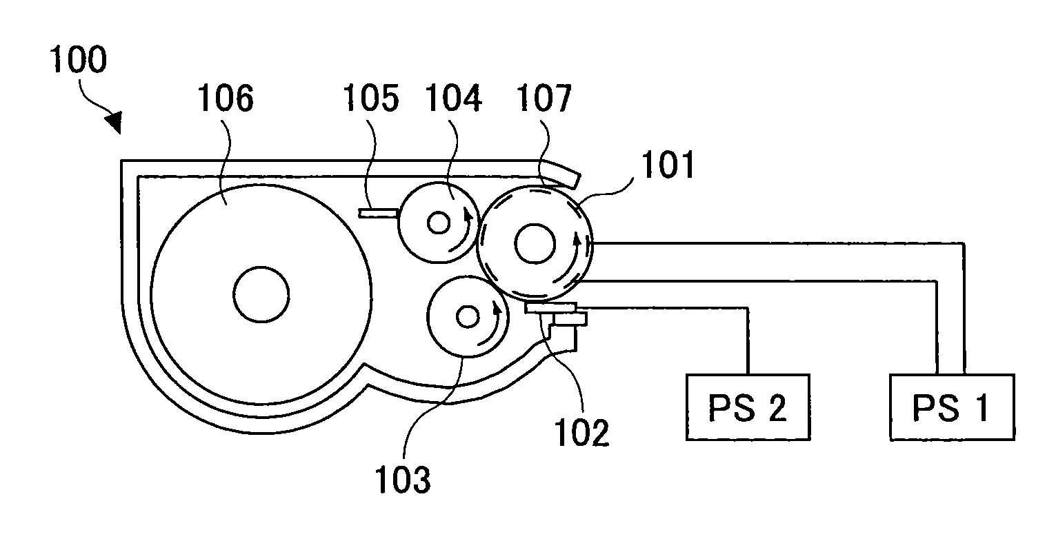
[0111]A toner contained in a toner container portion of the developing unit 100 is conveyed by a stirring paddle 106 to a supply roller 103. By rotating the supply roller 103 in a direction opposite to the rotation of a flare roller 101, the supply roller 103 also functions as a collection roller. The supply / collection functions may be independently provided, as in the example shown in FIG. 2.

[0112]As the toner is supplied to the flare roller 101, the toner is triboelectrically charged. The toner is then conveyed as the flare roller 101 rotates, while the amount of toner that becomes attached to the flare roller 101 is regulated by a toner layer thickness regulating member 102, which in the example shown consists of an electrically conductive rubber blade. In another embodiment, the regulating member 102 may be in the form of a roller.

[0113]The limited amount of the toner is uniformly rearranged while it hops over the f...

example 2

[0124]In Example 2, a rectangular wave shown in FIG. 6A was used as the drive waveform for causing the toner to hop.

[0125]The rectangular wave for one phase had an average value V0 of −300 V, frequency f of 1 kHz, and a peak-to-peak voltage Vpp of 600 V. The bias for the other phase had a DC bias V0 of −300 V. Thus, a constant voltage was applied to one phase of electrodes, and the rectangular wave voltage was applied to the other phase of electrodes. In this case, too, it was possible to cause the toner to hop.

[0126]By thus using a DC bias as one of the biases applied to the flare roller 101, the number of power supply systems for producing pulses can be reduced by one, so that a power supply cost reduction can be achieved.

[0127]To the toner layer thickness regulating member 102, the DC bias of V0 was applied.

[0128]Thus, by equalizing the potential of the bias applied to the toner layer thickness regulating member and the average value of the biases applied to the flare roller 101,...

example 3

[0129]In Example 3, as the drive waveforms for causing the toner to hop, the rectangular waves shown in FIG. 6B were used. Specifically, the rectangular waves of opposite phases with an average value V0 of −300 V, frequency f of 1 kHz, and a peak-to-peak voltage Vpp of 300 V, were applied.

[0130]To the toner layer thickness regulating member 102, a rectangular wave bias with an average value V0 of −300 V, frequency f2 of 500 Hz, and a peak-to-peak voltage V2 of 400 V was applied.

[0131]Under these conditions, when the flare roller 101 was continuously rotated, a constant cloud potential was obtained. Thus, good image formation was conducted without image density irregularities.


PUM


Abstract

A disclosed developing apparatus employs a flare roller that is a toner carrier in which electrodes of two different phases are provided at fine intervals. Density irregularities or scumming in a developed image due to a potential difference between the flare roller and a latent image carrier are prevented by maintaining a constant potential on the flare roller surface. A voltage is applied to the electrodes on the flare roller such that an electric field that varies with time is generated between the electrodes, whereby a toner cloud is produced by the movement or hopping of toner over the flare roller. Thereby the toner attaches to a latent image on the latent image carrier, thus developing the latent image. In one embodiment, a bias with an average potential equal to an average potential of the bias applied to the electrodes is applied to a toner layer thickness regulating member.

Description

BACKGROUND OF THE INVENTION[0001]1. Field of the Invention[0002]The present invention generally relates to the development of an electrostatic latent image on a latent image carrier in electrophotographic systems. More specifically, the invention relates to a cloud development method whereby a toner cloud is electrically produced.[0003]2. Description of the Related Art[0004]A developing unit used in a conventional image forming apparatus, such as a copy machine, a printer, or a FAX machine, may employ a two-component developing method or a one-component developing method. The two-component developing method is suitable for high-speed development, and is employed in the majority of the current middle- to high-speed image forming apparatuses.[0005]In the two-component developing method, in order to achieve a high image quality, it is necessary to make the developer, which typically consists of a toner formulation and magnetic material called a carrier, very fine and dense at the point...

Claims


Application Information

Patent Timeline
Patent Type & Authority Applications(United States)
IPC IPC(8): G03G15/08
CPCG03G15/0803G03G2215/0634G03G15/0818
Inventor ISHII, YASUYUKIKOSUGI, HIDEKITAKAHASHI, TOMOKOYAMADA, MASAAKIKADOTA, ICHIRONAKAGAWA, YOSHINORI
Owner RICOH KK
Why Eureka
Try Eureka