
Connector terminal

Inactive Publication Date: 2009-02-05
SMK CORP
View PDF2 Cites 17 Cited by
  • Summary
  • Abstract
  • Description
  • Claims
  • Application Information

AI Technical Summary

Benefits of technology

[0008]In light of the technological problems noted above, it is an object of the present invention to provice a connector terminal that can be inserted and installed without directionality in the peripheral direction with respect to the insertion direction during insertion and assembly of the connector terminal in the terminal storage chamber of the connector housing, as well as a connector terminal with excellent conductivity.
[0011]With the connector terminal according to the present invention, at least one of the stabilizers in the three or more directions along the periphery of the connector terminal cannot be cut from the plate material that forms the terminal housing body, and compared to conventional cases in which all stabilizers are formed through cutting for the purpose of outwardly bending and forming the insulation part to align with the plate material, in the case of the present invention, there are few increases in electrical resistance as a result of forming using a cutting process, and therefore excellent conductivity is achieved.

Problems solved by technology

However, when as many as three stabilizers 113 are cut into the terminal housing body 111, the cross-sectional area needed for conductivity within the terminal housing body is reduced because of the notch that is provided in order to make the cut, which is unfavorable in cases where large amounts electrical current are used.
In Published Unexamined Japanese Patent Application No. 2006-216324, a technology is disclosed in which a stabilizer is formed by stretching the plate material insulation part of the terminal housing body, but because of the inevitable need for engaging the stabilizer in a guide groove, the directional movement that occurs after installation adversely affects the assembly process.

Method used


Image

  • Connector terminal
  • Connector terminal
  • Connector terminal

Examples


Embodiment Construction

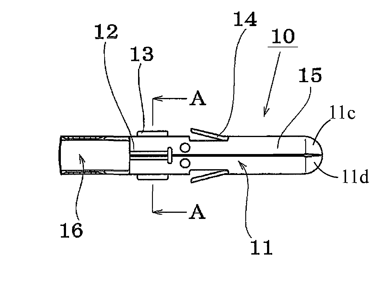
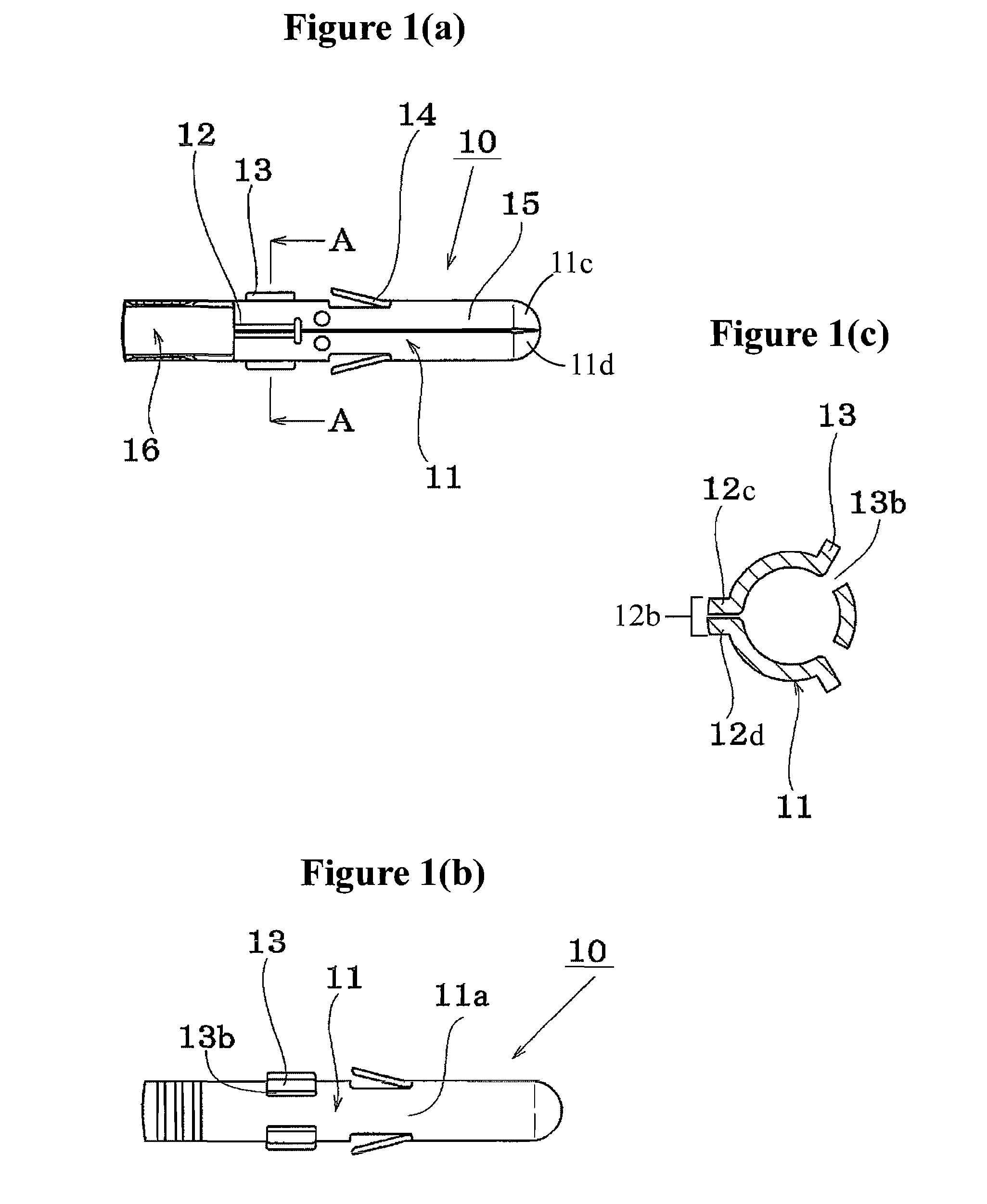
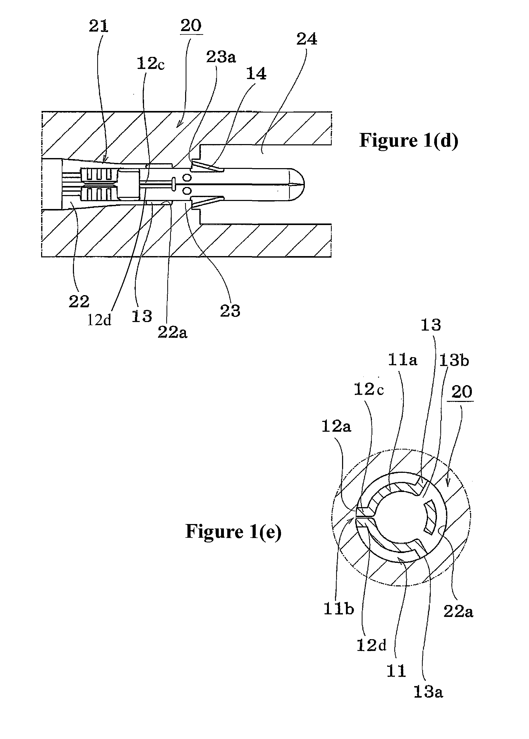
[0021]The following listing provides a key to the reference numerals and elements depicted in the drawings.[0022]10: Plug-type connector terminal[0023]11: Connector housing body[0024]11a: Side wall of connector housing body[0025]11b: Aligning part for plate material[0026]12: Stabilizer formed through extension of the plate material insulation part[0027]12a: Outer end of stabilizer[0028]13: Stabilizer formed through a cut-away process[0029]13a: Outer end of stabilizer[0030]13b: Notch[0031]14: Lance[0032]15: Contact part[0033]16: Electric line connection part[0034]20: Connector housing[0035]21: Terminal storage chamber[0036]22: Electric line storage part[0037]22a: Side wall of electric line storage part[0038]23: Circular convex part[0039]23a: Lance clip part[0040]24: Connection space part

[0041]The connector terminal construction according to the present invention can be widely applied to connectors that are inserted and assembled in housings, and FIGS. 1(a)-(d) show explanatory drawin...


PUM


Abstract

A connector terminal for insertion in a terminal storage chamber of a connector housing has a terminal housing body that is formed by bending a plate material into a somewhat cylindrical form. A plurality of stabilizers are erected in at least three positions directed radially away from a centerline running along an insertion direction of the terminal housing body such that the terminal housing body is rotatable about the centerline. At least one stabilizer is formed by outwardly bending a portion of the plate material that runs along the insertion direction of the terminal housing body, and at least another stabilizer is formed by making a cut from the side wall of the terminal housing body.

Description

CROSS-REFERENCE TO RELATED APPLICATION[0001]The present application claims priority from Japanese Patent Application No. JP2007-199857, which was filed on Jul. 31, 2007 and is hereby incorporated by reference in its entirety herein.FIELD OF THE INVENTION[0002]The present invention relates to a connector terminal construction that is inserted and installed within a connector housing.BACKGROUND OF THE INVENTION[0003]An example of a connector terminal that is inserted and assembled in the connector housing is shown in the external view in FIG. 3(a), and FIG. 3(b) shows an enlarged view of a cross-sectional end face of view B-B, in which a publicly known form of a connector terminal 110 has been formed by bending a plate material into a somewhat cylindrical form with a cross-sectional ring shape. This connector 110 has a lance 114 and stabilizer 113 that are formed through a cut in the side wall of the terminal housing body 111 in the intermediate space along the insertion direction of ...

Claims


Application Information

Patent Timeline
IPC IPC(8): H01R13/05
CPCH01R13/052H01R43/16H01R13/432
Inventor ARAI, ATSUSHI
Owner SMK CORP
Learn More