Process for producing conjugated polymer

a technology of conjugated polymer and process, which is applied in the direction of chemistry apparatus and processes, solid-state devices, and light-emitting compositions, etc., can solve the problems of discoloration of polymer products and decomposition of catalysts, and achieve superior properties and productivity, shorten reaction time, and improve the effect of efficiency

Inactive Publication Date: 2009-02-05
HITACHI CHEM CO LTD
View PDF7 Cites 15 Cited by
  • Summary
  • Abstract
  • Description
  • Claims
  • Application Information

AI Technical Summary

Benefits of technology

[0008]The present invention aims to resolve these concerns. In other words, an object of the present invention is to provide a process for producing a polymer that enables a significant shortening of the reaction time. Furthermore, another object of the present invention is to provide an organic electronics material, an electroluminescent material and an electroluminescent device that uses such an electroluminescent material which, when compared with the case using a conventional Suzuki coupling, exhibit superior properties and productivity.

Problems solved by technology

When the reaction time is this long, concerns arise over discoloration of the polymer product and decomposition of the catalysts.

Method used


Image

  • Process for producing conjugated polymer
  • Process for producing conjugated polymer
  • Process for producing conjugated polymer

Examples


examples

[0054]A more detailed description of the present invention is presented below using a series of examples, but the present invention is in no way limited by the following examples.

examples 1 to 16

Polymer Synthesis (1)

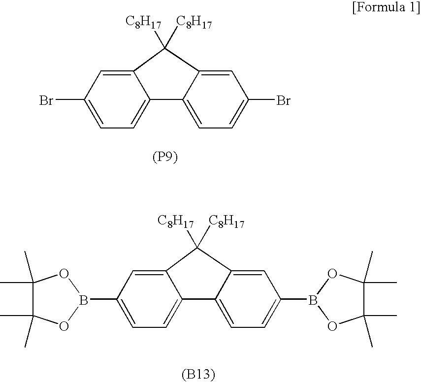
[0055]Reaction was conducted using a special-purpose polytetrafluoroethylene reaction vessel. The solvent was subjected to a treatment in which nitrogen gas was bubbled through the solvent for at least 30 minutes to remove oxygen prior to use. The reaction vessel was charged with 2,7-dibromo-9,9-dioctylfluorene (P9) (0.4 mmol) and the diboronate ester of 9,9-dioctylfluorene (B13) (0.4 mmol), and with the vessel placed in a glove box under an atmosphere of nitrogen, a 3 vol % toluene or anisole solution of tricaprylmethylammonium chloride (8 ml, see Table 1) and a 8 mM toluene or anisole solution of Pd(PPh3)4 (see Table 1) were then added to the vessel, thus yielding a mixture. Following stirring of the mixture to dissolve the monomers, a 2M aqueous base (5.3 ml, see Table 1) was added. The reaction vessel was then mounted in a microwave irradiation apparatus, and with the reaction mixture undergoing constant stirring, a Suzuki coupling reaction was conducted und...

examples 17 to 24

Polymer Synthesis (2)

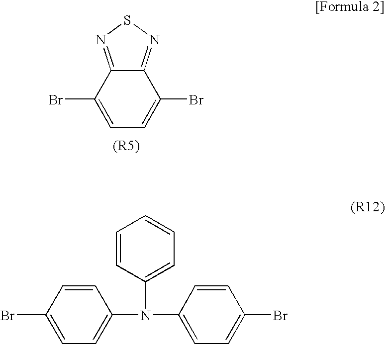
[0057]Reaction was conducted using a special-purpose polytetrafluoroethylene reaction vessel. The solvent was subjected to a treatment in which nitrogen gas was bubbled through the solvent for at least 30 minutes to remove oxygen prior to use. The reaction vessel was charged with 4,7-dibromo-2,1,3-benzothiazole (R5) (0.08 mmol), 4,4′-dibromotriphenylamine (R12) (0.32 mmol) and the diboronate ester of 9,9-dioctylfluorene (B13) (0.4 mmol), and with the vessel placed in a glove box under an atmosphere of nitrogen, a 3 vol % toluene or anisole solution of tricaprylmethylammonium chloride (8 ml, see Table 4) and a 8 mM toluene or anisole solution of Pd(PPh3)4 (see Table 4) were then added to the vessel, thus yielding a mixture. Following stirring of the mixture to dissolve the monomers, a 2M aqueous solution of K2CO3 (5.3 ml) was added. The reaction vessel was then mounted in a microwave irradiation apparatus, and with the reaction mixture undergoing constant stirrin...


PUM

PropertyMeasurementUnit
timeaaaaaaaaaa
frequencyaaaaaaaaaa
frequencyaaaaaaaaaa

Abstract

An object of the present invention is to provide a process for producing a conjugated polymer that enables a significant shortening of the reaction time. A process for producing a conjugated polymer according to the present invention is a process for producing a conjugated polymer by Suzuki coupling, wherein the process uses microwave irradiation. The conjugated polymer is preferably a polymer used as an organic electronics material, and is even more preferably a polymer used as an electroluminescent material.

Description

TECHNICAL FIELD[0001]The present invention relates to a process for producing a conjugated polymer. The present invention preferably relates to a process for producing a conjugated polymer used in an organic electronics material such as an electroluminescent device. Furthermore, the present invention also relates to an organic electronics material and an electroluminescent material produced using the above process for producing a conjugated polymer, and an electroluminescent device that uses the above electroluminescent material.BACKGROUND ART[0002]Electroluminescent devices are attracting considerable attention, for example as large-area solid state light sources capable of replacing incandescent lamps and gas-filled lamps. On the other hand, these materials are also attracting attention as the most promising self-luminous display capable of replacing liquid crystal displays within the field of flat panel displays (FPD). In particular, organic electroluminescent (EL) devices in whi...

Claims


Application Information

Patent Timeline
Patent Type & Authority Applications(United States)
IPC IPC(8): C08F214/18
CPCC08G61/00C09K11/06C09K2211/1416C09K2211/1466H01L51/5012H01L51/0036H01L51/0043H01L51/0077H01L51/0085C09K2211/1475H10K85/113H10K85/151H10K85/30H10K85/342H10K50/11H01L33/08
Inventor TSUDA, YOSHIHIROMORISHITA, YOSHIINOMURA, SATOYUKIHOSHI, YOUSUKEFUNYUU, SHIGEAKI
Owner HITACHI CHEM CO LTD
Why Eureka
Try Eureka