Vehicle drive assist system

a technology of vehicle drive and assist system, which is applied in the direction of steering initiation, instruments, vessel construction, etc., can solve the problems of ineffective response to risk and frequent increase of risk in the future, and achieve the effect of higher safety

Active Publication Date: 2009-02-05
SUBARU CORP
View PDF7 Cites 29 Cited by
  • Summary
  • Abstract
  • Description
  • Claims
  • Application Information

AI Technical Summary

Benefits of technology

[0017]A eighth aspect of the present invention according to the seventh aspect of the present invention, the risk correcting means corrects the current risk set by the risk setting means in accordance with the relative acceleration between the object and the vehicle so that the current risk increases as the relative acceleration increases in a direction in which the object approaches the vehicle.
[0018]According to the vehicle drive assist system of the present invention, it is possible to set not only the current risk, but also future risks. This allows the vehicle to be controlled so as to take an optimum route with higher safety.

Problems solved by technology

However, the control disclosed in the above publication is performed strictly in accordance with the current risk potential, and therefore, cannot effectively respond to the risk that varies with movements of the vehicle and the obstacle.
In other words, even in a path that is considered optimal at present, the risk will frequently increase in the future.

Method used


Image

  • Vehicle drive assist system
  • Vehicle drive assist system
  • Vehicle drive assist system

Examples


Embodiment Construction

[0026]An embodiment of the present invention will be described below with reference to FIGS. 1 to 7.

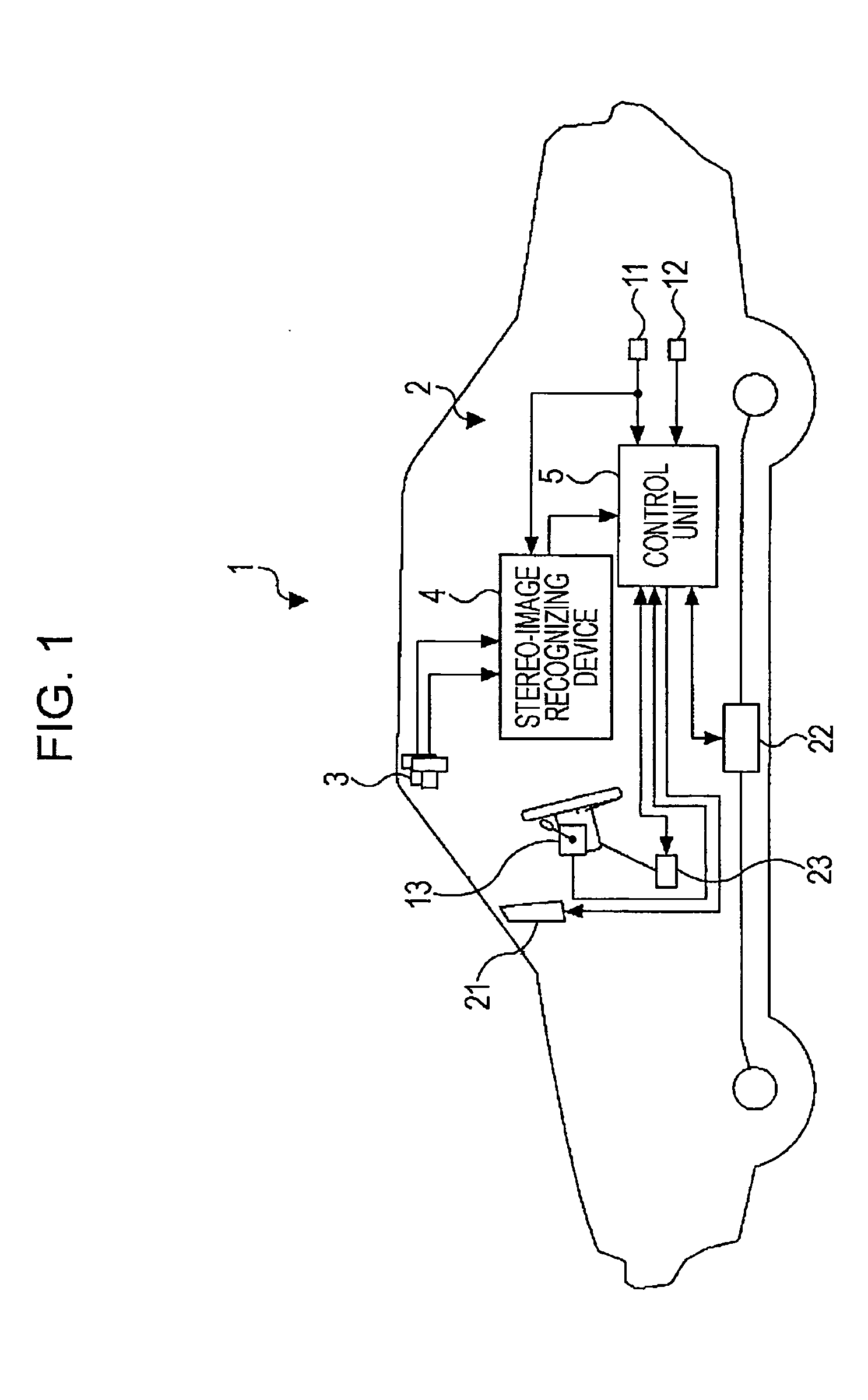
[0027]Referring to FIG. 1, a drive assist system 2 is installed in a vehicle (driver's own vehicle) 1 such as a car. The drive assist system 2 mainly includes a stereo camera 3, a stereo-image recognizing device 4, and a control unit 5.

[0028]The vehicle 1 is also provided with a vehicle speed sensor 11 for detecting the vehicle speed V, a yaw-rate sensor 12 for detecting the yaw rate (dφ / dt), and a main switch 13 to which an ON / OFF signal for drive assist control is input. The vehicle speed V is input to the stereo-image recognizing device 4 and to the control unit 5. The yaw rate (dφ / dt) and the ON / OFF signal for drive assist control are input to the control unit 5.

[0029]The stereo camera 3 serves as a stereo optical system, and includes a pair of (right and left) CCD cameras each using a solid-state image sensor such as a charge coupled device (CCD). The right and left CCD cameras a...


PUM


Abstract

A control unit sets a current total risk function for each of white lines, guardrails, side walls, and three-dimensional objects existing around a vehicle, estimates a temporal change in the position of each object, and calculates a minimum of the total risk function at the vehicle position for each time. An objective function is generated for the time, and a turning control amount that minimizes the objective function at the time is calculated as a turning control amount of the vehicle. Risk functions provided when the vehicle moves by the turning control amount are set for respective routes. A final avoidance route is selected from the risk functions of the routes, and steering and braking are controlled.

Description

CROSS-REFERENCES TO RELATED APPLICATIONS[0001]The disclosure of Japanese Patent Application No. 2007-033893 filed on Feb. 14, 2007 and No. 2007-155635 filed on Jun. 12, 2007 including the specification, drawings and abstract is incorporated herein by reference in it entirety.BACKGROUND OF THE INVENTION[0002]1. Field of the Invention[0003]The present invention relates to a vehicle drive assist system that sets risks for white lines and three-dimensional objects existing around a vehicle and detected, for example, by a stereo camera, a monocular camera, or a millimeter-wave radar and that controls steering or braking so that the vehicle can take an optimum route.[0004]2. Description of the Related Art[0005]In recent years, various technologies of improving safety of a vehicle have been developed and practically used. In these technologies, a traveling environment in front of the vehicle is detected, for example, by a camera or a laser radar mounted in the vehicle. On the basis of data...

Claims


Application Information

Patent Timeline
Patent Type & Authority Applications(United States)
IPC IPC(8): G08G1/16
CPCG08G1/167G08G1/16G08G1/165
Inventor OGASAWARA, TOYOKAZUTSUKASAKI, YUICHIRO
Owner SUBARU CORP
Why Eureka
Try Eureka