Vehicle behavior control device

a technology of vehicle behavior and control device, which is applied in the direction of underwater vessels, non-deflectable wheel steering, driver input parameters, etc., can solve problems such as difficulty in obtaining a target braking force, oversteer suppressing performance may deteriorate, and problems such as problems

Active Publication Date: 2009-02-05
SUBARU CORP
View PDF4 Cites 31 Cited by
  • Summary
  • Abstract
  • Description
  • Claims
  • Application Information

AI Technical Summary

Benefits of technology

[0009]The present invention has been made under such circumstances, and it is an object of the present invention to provide a vehicle behavior control device that can properly suppress an understeer condition and an oversteer condition while preventing interference between left-right driving-force distribution control and vehicle drive control for sideslip prevention even when the left-right driving-force distribution control is performed in combination with the vehicle drive control.
[0011]According to the vehicle behavior control device of the present invention, when the vehicle drive control for sideslip prevention is in operation, the driving-force distribution controlled in accordance with the left-right driving-force distribution control is adjusted such that the polarity of the yaw moment to be added to the vehicle is in the same direction as that of the yaw moment applied in accordance with the vehicle drive control. Consequently, an understeer condition and an oversteer condition can be properly suppressed while the left-right driving-force distribution control and the vehicle-drive control for sideslip prevention are prevented from interfering with each other even when the left-right driving-force distribution control is performed in combination with the vehicle-drive control.

Problems solved by technology

However, problems can occur if the left-right driving-force distribution control as disclosed in Japanese Unexamined Patent Application Publication No. 2006-29460 is performed in combination with vehicle drive control for controlling a vehicle for sideslip prevention, such vehicle drive control including controlling of the engine by opening and closing of the throttle valve and fuel cut and controlling of the braking force independently for the four wheels.
In that case, the oversteer suppressing performance may deteriorate, or the driving force applied in accordance with the left-right driving-force distribution control may interfere with the braking force, making it difficult to obtain a target braking force and thus deteriorating the oversteer suppressing performance.

Method used


Image

  • Vehicle behavior control device
  • Vehicle behavior control device
  • Vehicle behavior control device

Examples


first embodiment

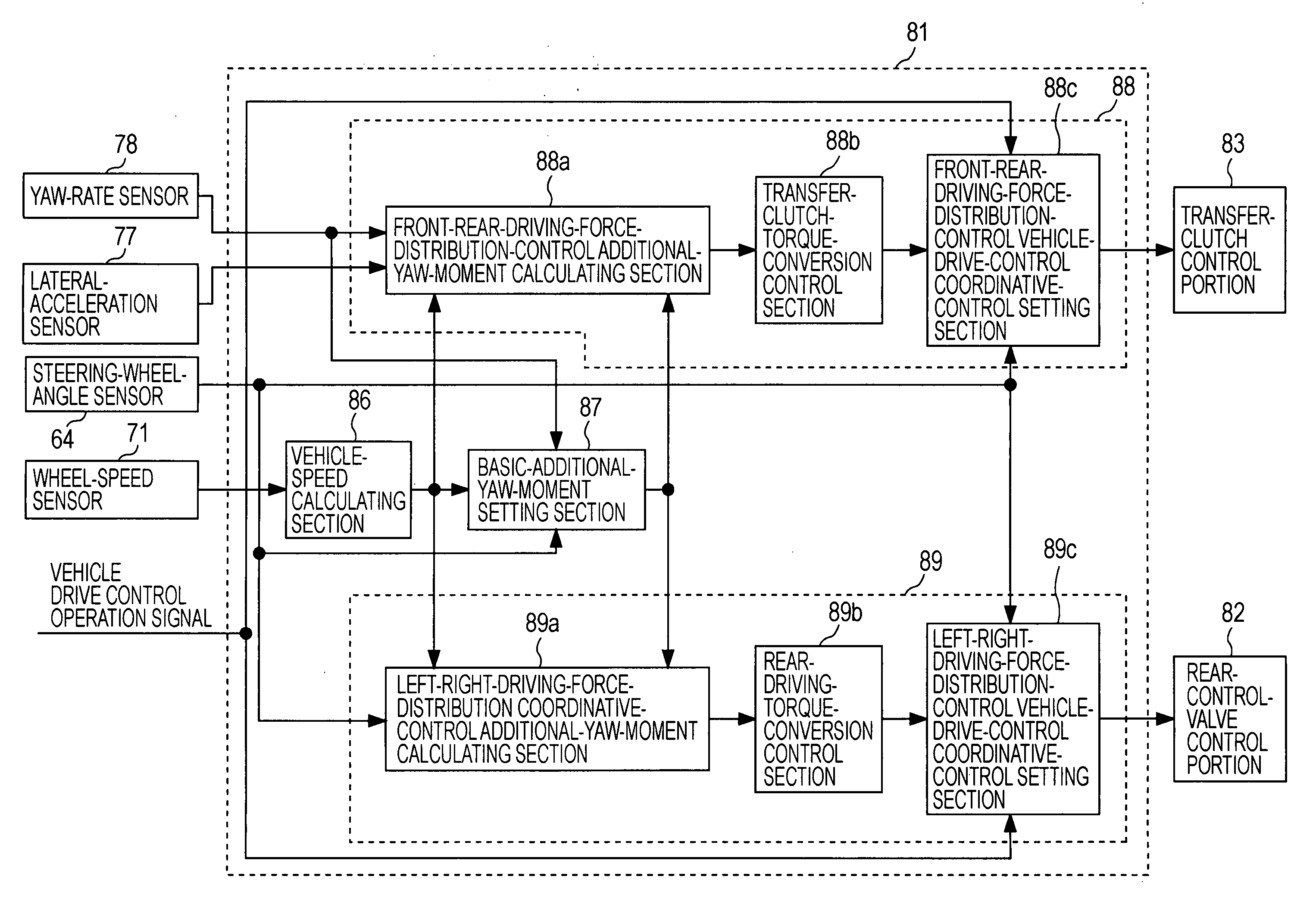
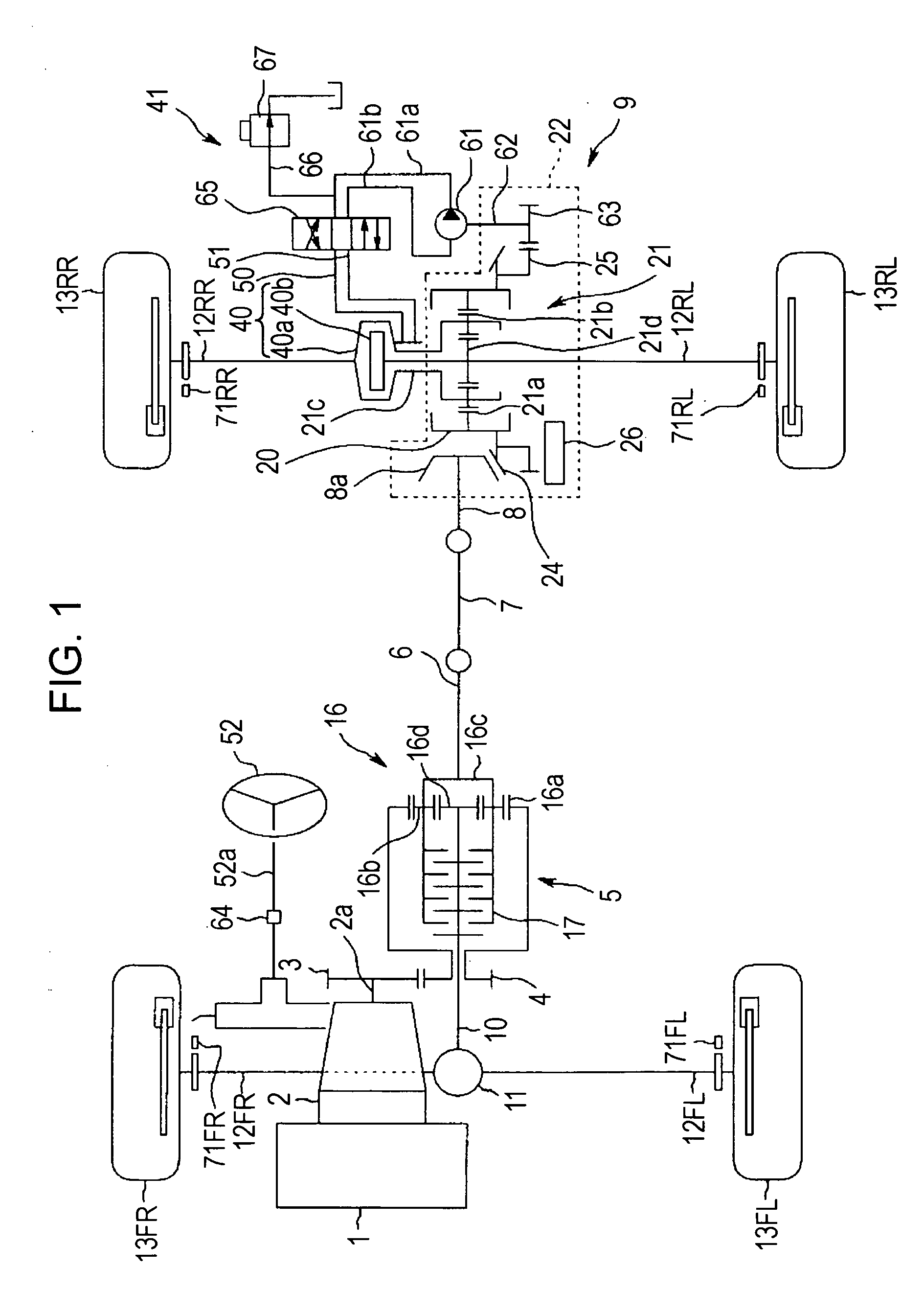
[0030]FIGS. 1 to 16 illustrate a first embodiment of the present invention. FIG. 1 is a schematic diagram of a vehicle behavior control device for a four-wheel-drive vehicle. FIG. 2 is a functional block diagram of a control unit. FIG. 3 is a functional block diagram of a driving-force distribution control portion.

[0031]Reference numeral 1 in FIG. 1 denotes an engine. A transmission 2 (automatic transmission or manual transmission) is linked to this engine 1. The output from the engine 1 undergoes predetermined gear change and torque amplification at the transmission 2 and is subsequently output from an output shaft 2a. The output shaft 2a is provided with a drive gear 3 that constitutes a power transmission system. The drive gear 3 is meshed with a driven gear 4 provided in a center differential device 5.

[0032]The center differential device 5 receives a driving force from the transmission 2 and distributes the driving force to the front and rear wheels. The center differential devi...

second embodiment

[0109]FIG. 17 is a functional block diagram of a driving-force distribution control portion according to a second embodiment of the present invention. In contrast to the first embodiment described above in which the steering-wheel angle OH is directly detected by the steering-wheel-angle sensor 64, the second embodiment is configured such that the steering-wheel-angle sensor 64 is omitted. Specifically, instead of the steering-wheel angle θH being detected by the steering-wheel-angle sensor 64, a steering-wheel angle is calculated on the basis of a lateral acceleration d2y in the second embodiment.

[0110]The second embodiment will be described below by focusing only on the differences from the first embodiment. Referring to FIG. 17, a driving-force-distribution control portion 81′ according to the second embodiment includes a steering-wheel-angle calculating section 64′. More specifically, the steering-wheel-angle calculating section 64′ provided as steering-wheel-angle detecting mea...


PUM


Abstract

A basic-additional-yaw-moment setting section sets a basic additional yaw moment and determines the polarity of the basic additional yaw moment on the basis of a steering-wheel angle, a yaw rate, and a vehicle speed. A left-right driving-force distribution controller sets the driving-force distribution with respect to left and right driving wheels on the basis of the basic additional yaw moment and the polarity of the basic additional yaw moment, and adjusts the driving-force distribution when a vehicle drive control operation signal is output from a vehicle drive control unit. Specifically, the left-right driving-force distribution control section adjusts the driving-force distribution such that the polarity of the basic additional yaw moment is in the same direction as that of a yaw moment applied by the vehicle drive control unit.

Description

CROSS REFERENCES TO RELATED APPLICATIONS[0001]The disclosure of Japanese Patent Application No. 2007-201134 filed on Aug. 1, 2007 including the specifications, drawings, and abstracts are incorporated by references herein.BACKGROUND OF THE INVENTION[0002]1. Field of the Invention[0003]The present invention relates to a vehicle behavior control device equipped with sideslip prevention controlling means that prevents a sideslip by controlling the vehicle and driving-force-distribution controlling means that controls driving-force distribution with respect to at least left and right driving wheels.[0004]2. Description of the Related Art[0005]In recent years, there have been proposed and put in practical use various technologies for vehicle-behavior control, which include braking-force control and driving-force distribution control. Specifically, driving-force distribution control involves controlling the driving force distributed to the front and rear wheels in addition to actively con...

Claims


Application Information

Patent Timeline
Patent Type & Authority Applications(United States)
IPC IPC(8): B62D6/00B60K17/35B60T8/1755B60W30/02F16H48/22F16H48/26F16H48/27F16H48/295F16H48/32F16H48/36F16H48/38
CPCB60K23/04B60W10/14B60W10/16B60W2520/20B60W2520/125B60W2520/14B60W2510/20B60W2540/18
Inventor YAMAZAKI, YOSHINOBU
Owner SUBARU CORP
Why Eureka
Try Eureka