Gas sensor, air-fuel ratio controller, and transportation apparatus

a technology of air-fuel ratio and gas sensor, which is applied in the field of gas sensors, can solve the problems of adding to production costs, difficult to control the air-fuel ratio with a high precision, and inability to control the temperature of the sensor, etc., and achieves the effect of accurate and simple manner

Inactive Publication Date: 2009-02-12
YAMAHA MOTOR CO LTD
View PDF5 Cites 9 Cited by
  • Summary
  • Abstract
  • Description
  • Claims
  • Application Information

AI Technical Summary

Benefits of technology

[0021]In order to overcome the problems described above, preferred embodiments of the present invention provide a gas sensor which can compensate for an error in the resistance value of a heater in an accurate and simple manner.

Problems solved by technology

This may lead to being unable to control the sensor temperature to be within the desired range.
In the case where a resistance-type gas detection section is used, the sensor output has high temperature dependence, and therefore this problem would make it difficult to control the air-fuel ratio with a high precision.
However, performing a correction for each gas sensor as disclosed in Japanese Laid-Open Patent Publication No. 2000-180406 would complicate the production steps, thus adding to the production cost.
In the case of adopting the technique disclosed in Japanese Laid-Open Patent Publication No. 2000-2678, it is necessary to provide both a means for measuring the inrush current and a means for measuring the applied voltage; and, in practice, the heater temperature will keep increasing in the short time during which these measurements are taken, which makes it difficult to accurately calculate the heater resistance value at room temperature.
It might be possible to implement a calculation program in a microcomputer that supports a heater resistance value (resistance value at room temperature) which differs from gas sensor to gas sensor, however, such a technique would be very complicated and unpractical.

Method used


Image

  • Gas sensor, air-fuel ratio controller, and transportation apparatus
  • Gas sensor, air-fuel ratio controller, and transportation apparatus
  • Gas sensor, air-fuel ratio controller, and transportation apparatus

Examples


Embodiment Construction

[0057]Hereinafter, preferred embodiments of the present invention will be described with reference to the accompanying drawings. Although an oxygen sensor for detecting oxygen preferably is exemplified below, the present invention is not limited to an oxygen sensor, but can be suitably used for gas sensors including a heater.

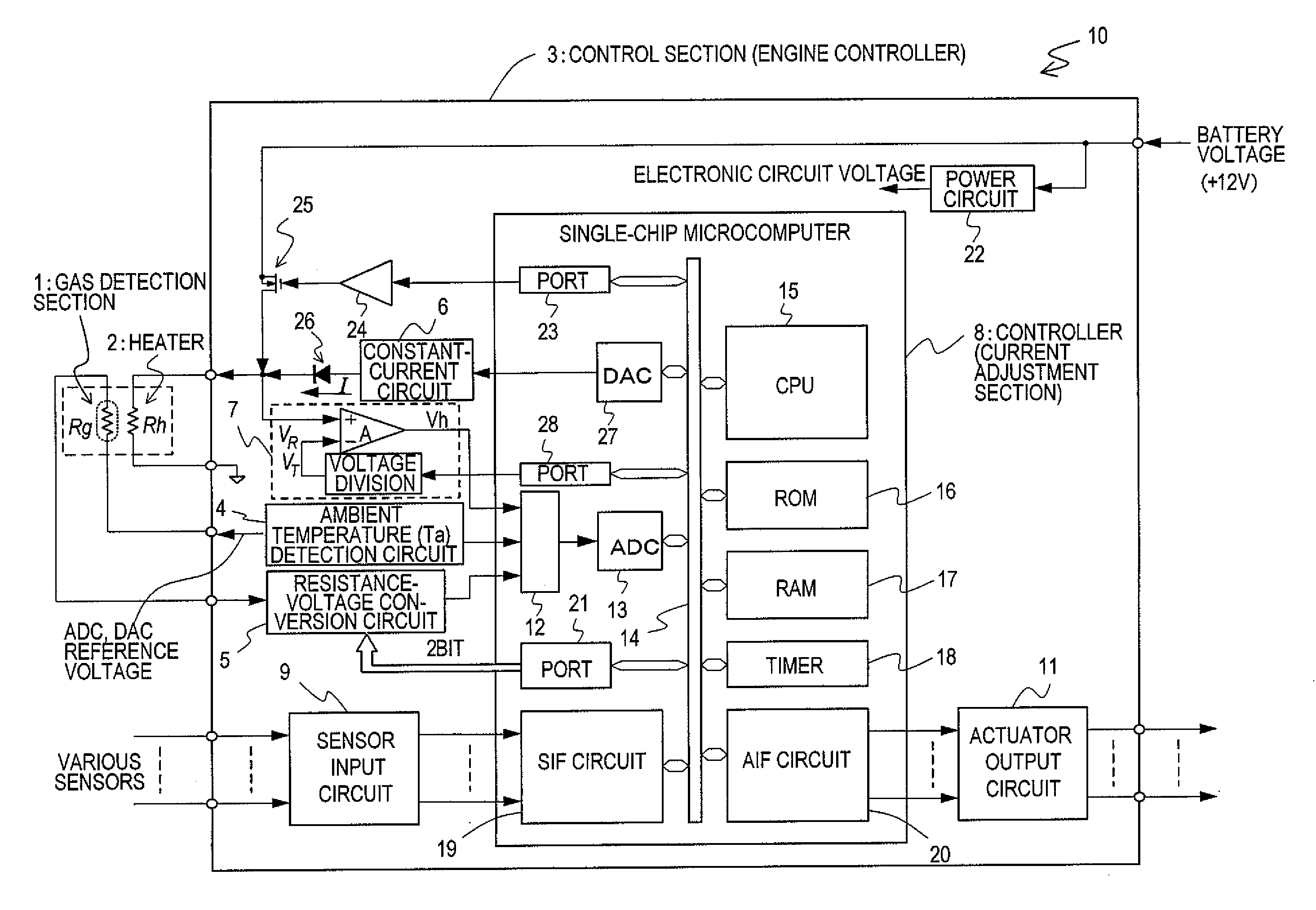
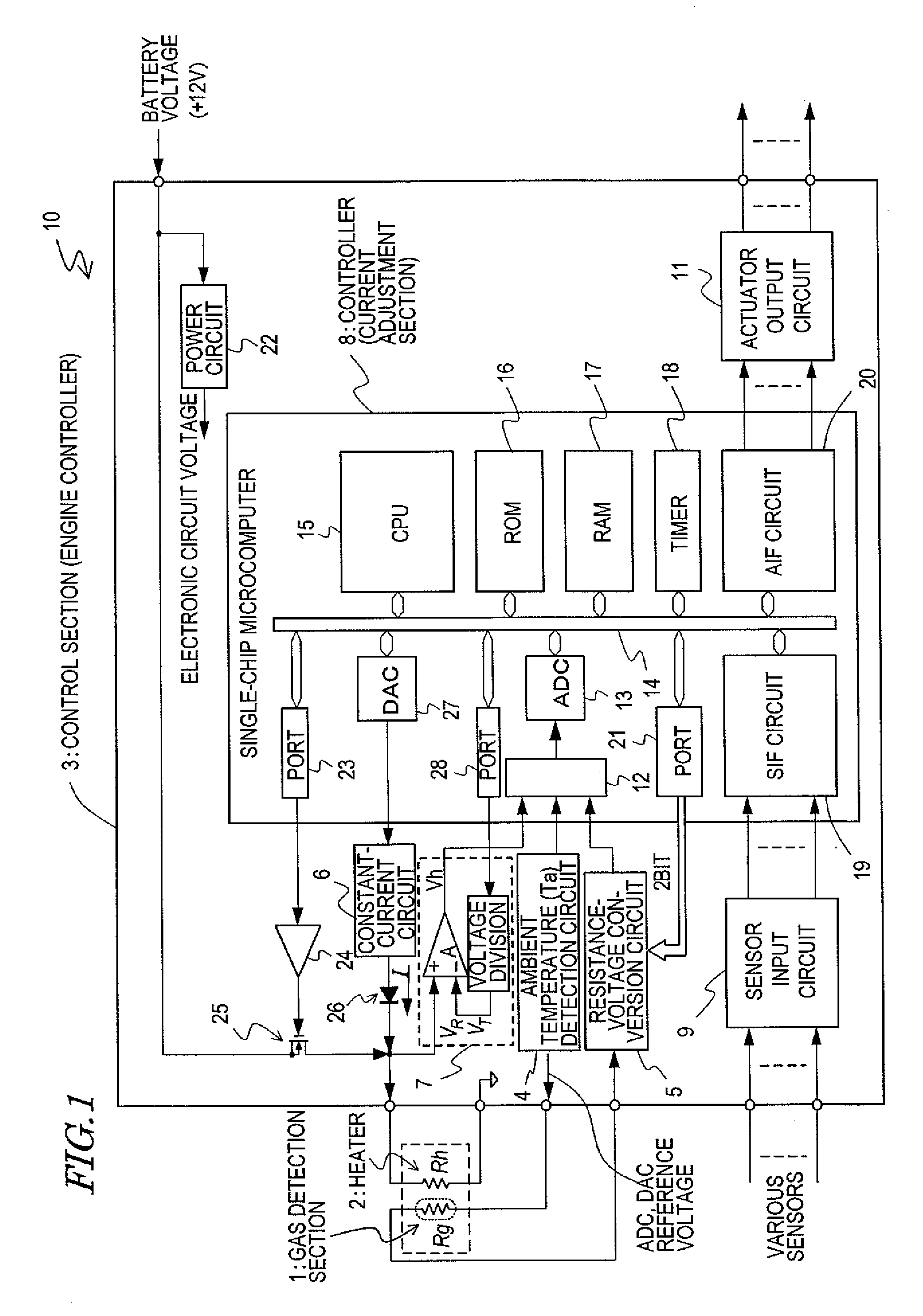
[0058]FIG. 1 is a circuit diagram showing the construction of an oxygen sensor 10 according to a preferred embodiment of the present embodiment. As shown in FIG. 1, the oxygen sensor 10 includes a gas detection section 1, a heater 2 for elevating the temperature of the gas detection section 1, and a control section 3 for controlling the operation of the heater 2.

[0059]The gas detection section 1 detects the concentration and / or amount of a predetermined gas that is contained in an atmosphere which is in contact with the gas detection section 1. The gas detection section 1 of the present preferred embodiment is a so-called resistance type, whose resistance value ...


PUM


Abstract

A gas sensor includes a gas detection section, a heater whose electrical resistance value changes in accordance with temperature, and a control section arranged to control an operation of the heater and to perform powering of the heater for heating. The control section includes a current supply section to supply a current to the heater in a period during which powering of the heater for heating is stopped, a voltage detection section arranged to detect an end-to-end voltage of the heater while a current is being supplied to the heater from the current supply section, and a current adjustment section arranged to adjust the level of the current, during a cold period of the heater, which is supplied from the current supply section based on an ambient temperature and the end-to-end voltage of the heater as detected by the voltage detection section.

Description

BACKGROUND OF THE INVENTION[0001]1. Field of the Invention[0002]The present invention relates to a gas sensor, and in particular to a gas sensor having a heater arranged to elevate the temperature of a gas detection section. The present invention also relates to an air-fuel ratio controller and a transportation apparatus incorporating such a gas sensor.[0003]2. Description of the Related Art[0004]From the standpoint of environmental and energy issues, it has been desired to improve the fuel consumption of internal combustion engines, and reduce the emission amount of regulated substances (e.g., NOx) that are contained within exhaust gas from internal combustion engines. In order to meet these needs, it is necessary to appropriately control the ratio between fuel and air in accordance with the state of combustion, so that fuel combustion will occur always under optimum conditions. The ratio of air to fuel is called an “air-fuel ratio” (A / F). In the case where a ternary catalyst is em...

Claims


Application Information

Patent Timeline
Patent Type & Authority Applications(United States)
IPC IPC(8): F01N3/00
CPCG01N27/122
Inventor OH-HORI, NORIKOSUZUKI, TOSHIO
Owner YAMAHA MOTOR CO LTD
Why Eureka
Try Eureka