Method and device for operating an internal combustion engine

Active Publication Date: 2009-02-12
ROBERT BOSCH GMBH
View PDF9 Cites 13 Cited by
  • Summary
  • Abstract
  • Description
  • Claims
  • Application Information

AI Technical Summary

Benefits of technology

[0012]The reliability of the error recognition is further increased in that the at least one operating state of the internal combustion engine is recognized as present only if the mass flow or the mass flow rat

Problems solved by technology

If the determined value of the characteristic quantity for the functioning of the exhaust ga

Method used


Image

  • Method and device for operating an internal combustion engine
  • Method and device for operating an internal combustion engine
  • Method and device for operating an internal combustion engine

Examples


Embodiment Construction

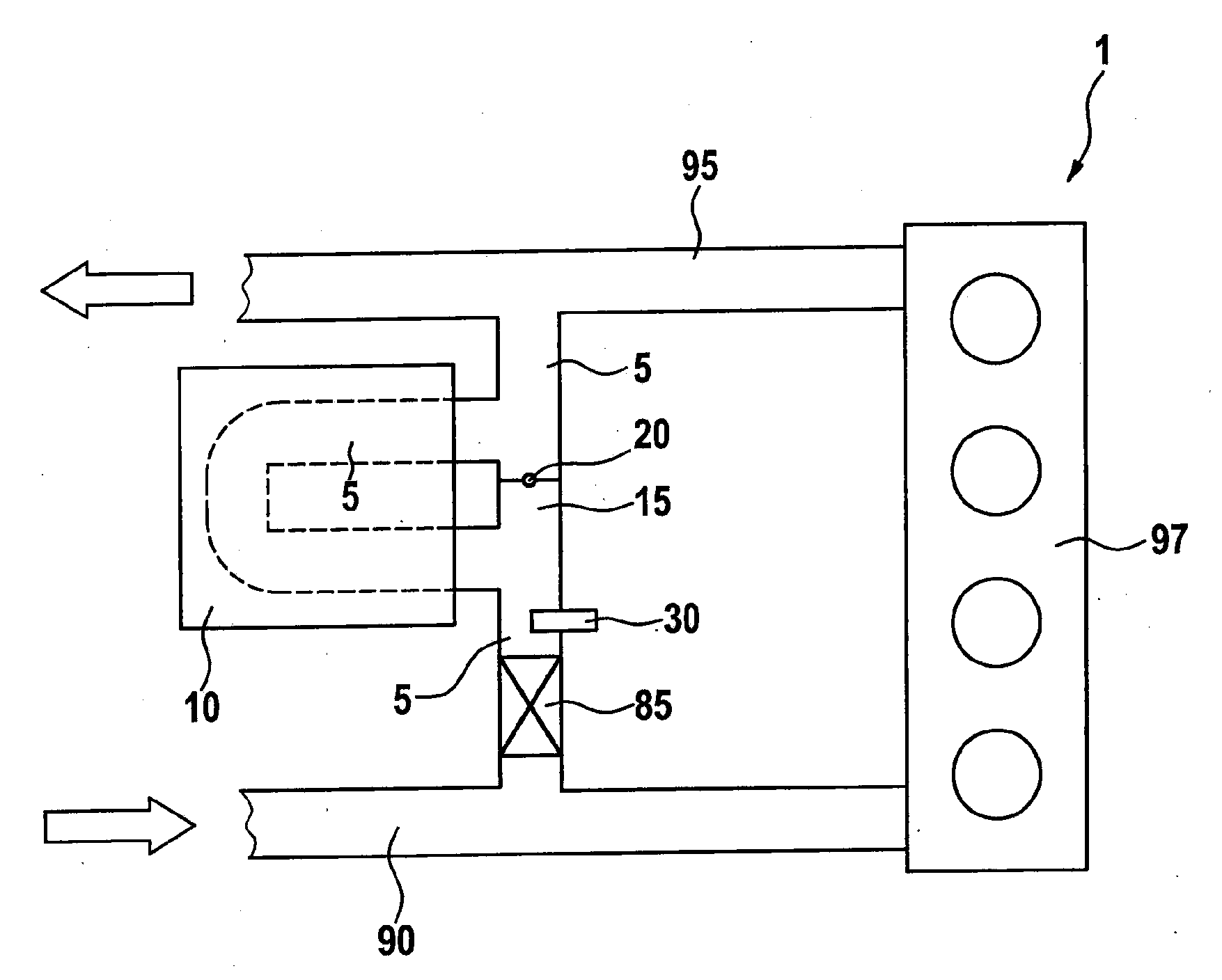
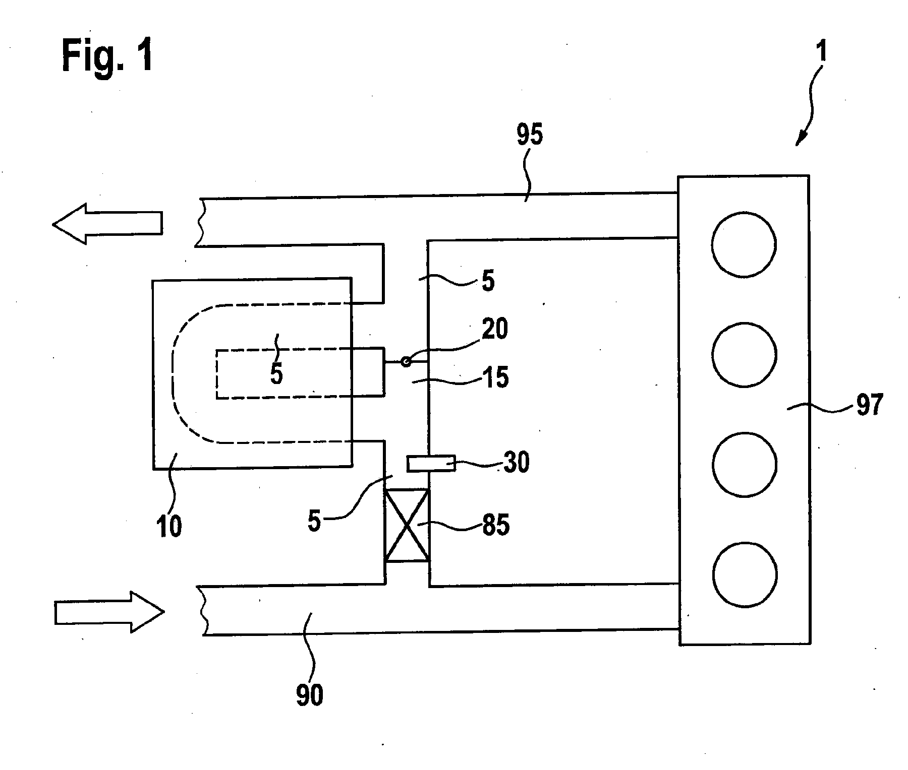
[0018]In FIG. 1, 1 designates an internal combustion engine. Internal combustion engine 1 can be for example a gasoline engine or a diesel engine. An engine block 97 of internal combustion engine 1 is supplied with air via an air supply 90. This air is combusted together with fuel in the combustion chambers of engine block 97. The resulting exhaust gas is expelled into an exhaust-system branch 95. Internal combustion engine 1 can for example drive a vehicle. Via an exhaust gas recirculation line 5, part of the exhaust gas is branched off from exhaust-system branch 95 and supplied to air supply 90. Exhaust gas recirculation line 5 is here routed through a cooling device 10 in order to cool the recirculated exhaust gas. Exhaust gas recirculation line 5, guided through cooling device 10, is bridged by a bypass or bypass channel 15 having a bypass valve 20. When bypass valve 20 is closed, as is shown in FIG. 1, the recirculated exhaust gas flows entirely via exhaust gas recirculation li...


PUM


Abstract

A method and a device for operating an internal combustion engine having at least one mass flow line and a cooling device for cooling the mass flow in the mass flow line, as well as a bypass, having a bypass valve, that bypasses the cooling device. When the bypass valve is opened, the mass flow is conducted at least partly through the bypass. When the bypass valve is closed, the mass flow is conducted through the cooling device. Downstream from the cooling device and from the bypass in the mass flow line, a temperature of the mass flow in the mass flow line is determined. In at least one operating state of the internal combustion engine, a first temporal temperature gradient is determined with closed bypass valve. In the at least one operating state of the internal combustion engine, a second temporal temperature gradient is determined with closed position of the bypass valve. An error is recognized as a function of a deviation between the first temporal temperature gradient and the second temporal temperature gradient.

Description

CROSS REFERENCE[0001]This application claims the benefit under 35 U.S.C. § 119 of German Patent Application No. 102007036258.9 filed on Aug. 2, 2007, the entirety of which is expressly incorporated herein by reference.FIELD OF THE INVENTION[0002]The present invention relates to a method and a device for operating an internal combustion engine.BACKGROUND INFORMATION[0003]German Patent Application No. DE 10 2004 041 767 A1 describes a method and a device for operating an internal combustion engine having an exhaust gas recirculation system that enables a diagnosis of an exhaust gas recirculation cooling device during normal operation of the internal combustion engine. Here, a characteristic quantity for the functioning of the exhaust gas recirculation cooling device is monitored. The characteristic quantity for the function of the exhaust gas recirculation cooling device is determined as a function of a measurement value. The characteristic quantity for the functioning of the exhaust ...

Claims


Application Information

Patent Timeline
IPC IPC(8): F02M25/07
CPCF02D41/0055F02D2041/0067F02M25/0702Y02T10/121F02M25/0754F02M25/0756F02M25/0728F02M26/48F02M26/49F02M26/25F02M26/47
Inventor BLUMENDELLER, WILHELM
Owner ROBERT BOSCH GMBH
Why Eureka
Try Eureka