
Apparatus for stabbing pipe when using an iron roughneck

a technology of roughneck and iron rod, which is applied in the direction of drilling pipes, drilling casings, borehole/well accessories, etc., can solve the problems of inherently decreasing cycle time, and achieve the effects of reducing cycle time, reducing cycle time, and being convenient to us

Inactive Publication Date: 2009-02-12
FORUM US
View PDF8 Cites 3 Cited by
  • Summary
  • Abstract
  • Description
  • Claims
  • Application Information

AI Technical Summary

Benefits of technology

The present invention provides a way to stab drill pipe and drill collars using an iron roughneck in a cost-effective and versatile way. It involves a pipe engagement mechanism that restrains the movement of the pipe while allowing it to move vertically. This mechanism can be moved out of the way when the iron roughneck is connected to the drill string, which speeds up the process and reduces the risk of accidents. The invention also allows for faster and safer tripping of the drill string by moving the iron roughneck and engaging the pipe stand with the stabbing device in a quick and efficient way.

Problems solved by technology

Since this portion of the operation is normally a mostly “idle time” for the floor personnel, any operations that may be moved to this period will inherently decrease the cycle time.

Method used


Image

  • Apparatus for stabbing pipe when using an iron roughneck
  • Apparatus for stabbing pipe when using an iron roughneck
  • Apparatus for stabbing pipe when using an iron roughneck

Examples


Embodiment Construction

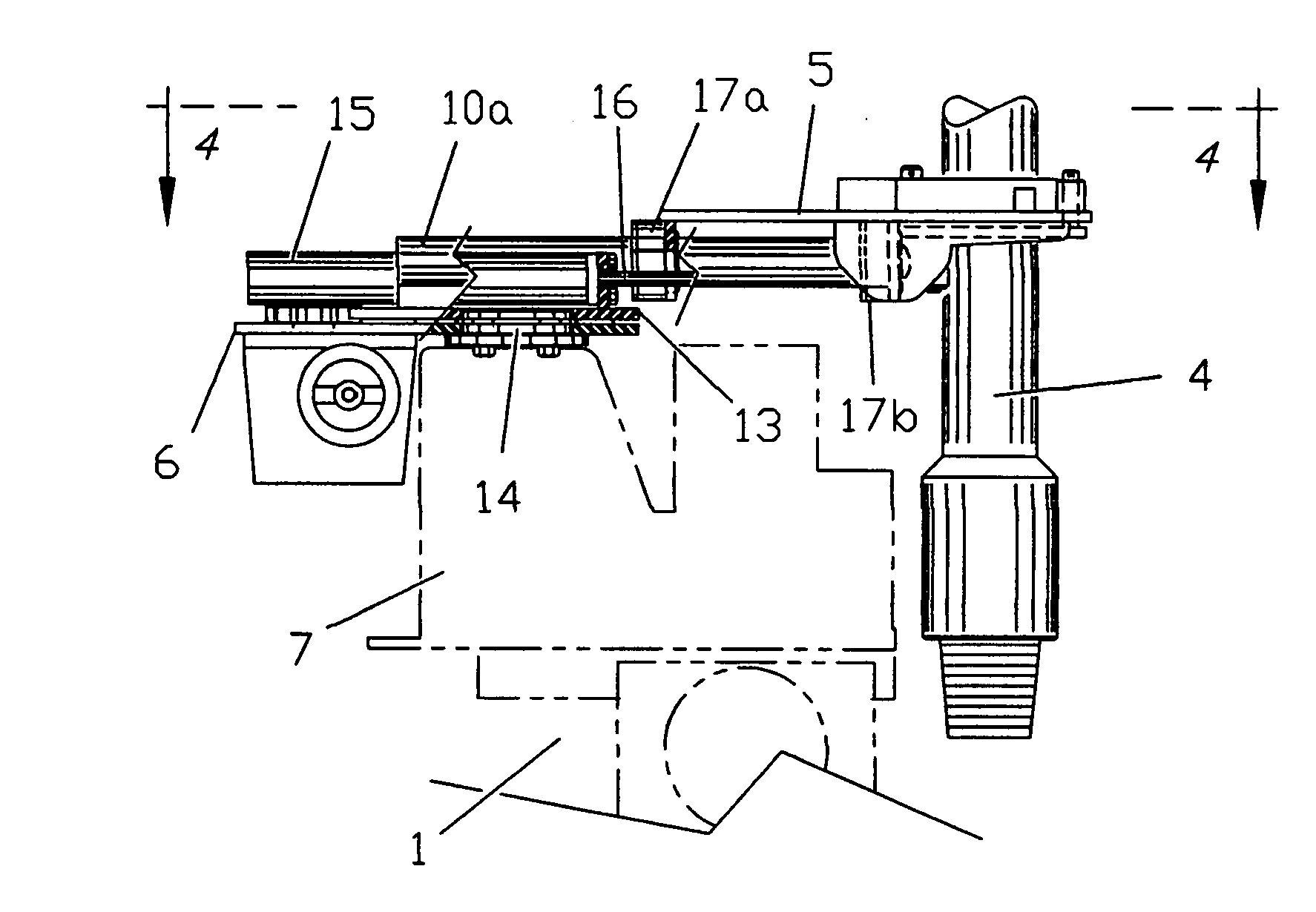
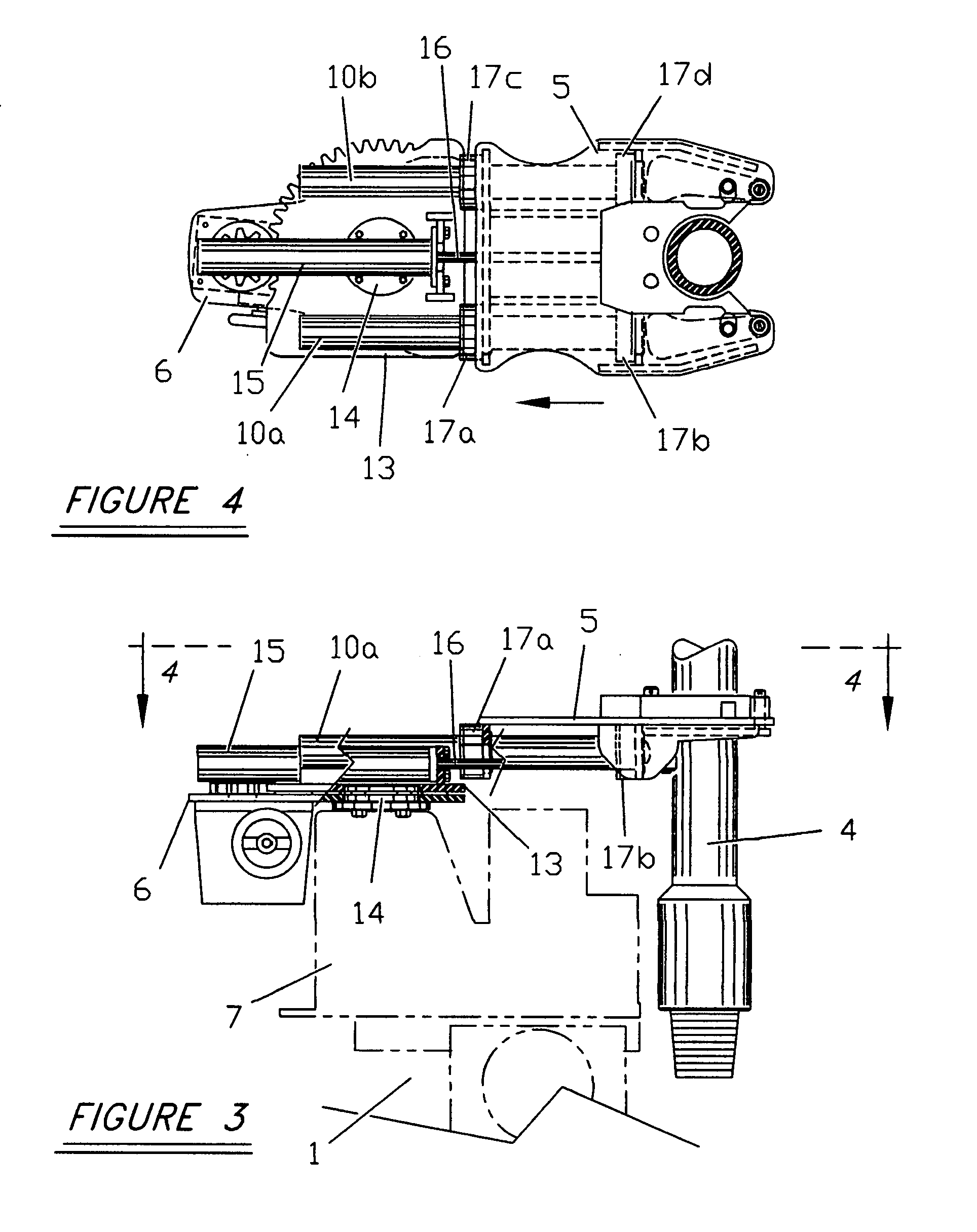
[0008]The preferred embodiment of a pipe stabbing device of the present invention is shown is the appended drawings and as described herein. In all cases, the pipe stabbing device of the present invention is mounted above the upper wrench assembly of the iron roughneck. Depending on the configuration of the iron roughneck, the pipe stabbing device of the present invention may be mounted above or below the pipe spinner portion of the iron roughneck.

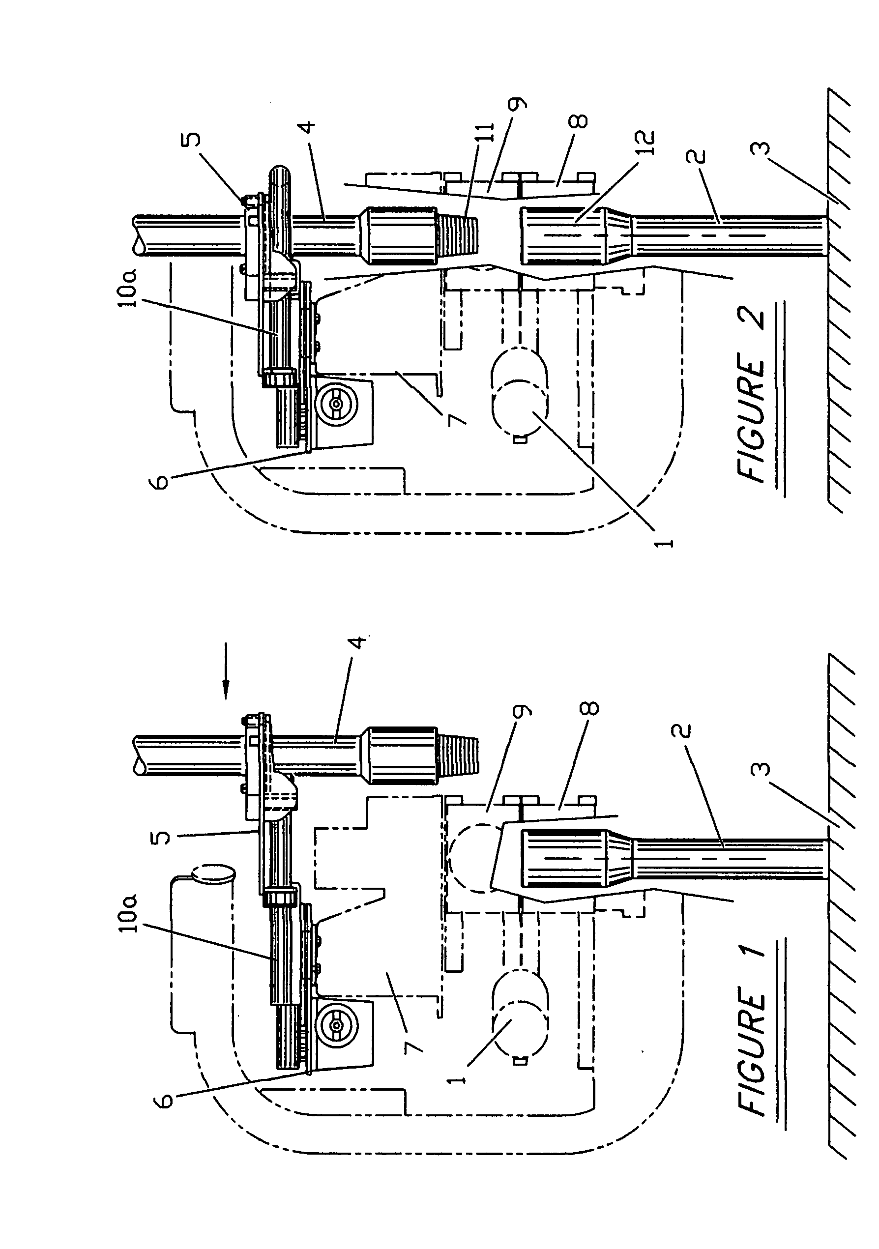
[0009]FIG. 1 illustrates the stationary base 6 of a pipe stabbing device of the present invention mounted atop the spinner portion 7 of the iron roughneck 1. The lower wrench 8 of the iron roughneck 1 is shown positioned and clamped onto the uppermost tool joint box of drill string 2 suspended in the well bore. The drill string 2 is supported by the rig structure 3. Further shown is the lower end of the pipe stand to be added 4 in initial engagement with the extended pipe engagement mechanism 5. The pipe engagement mechanism 5 is supported...


PUM


Abstract

Drilling apparatus for receiving, moving and aligning pipe sections as they are added to a string of pipe on a drilling rig when using an iron roughneck. After the iron roughneck is moved to well centerline and engaged with the box connection of the pipe suspended in the well bore, a hydraulically controlled pipe engagement mechanism is extended radially away from the iron roughneck and in the general direction of the pipe rack. Said pipe engaging mechanism receives the lower end of the next stand of pipe to be added and is the hydraulically retracted to lock around said pipe stand and bring said pipe stand into alignment with the pipe string suspended in the well bore.

Description

FIELD OF THE INVENTION[0001]This invention relates generally to rotary drilling apparatus for oil and gas wells and in particular to an apparatus for stabbing drill pipe and other tubular products used in drilling wells when using an iron roughneck machine.BACKGROUND OF THE INVENTION[0002]Rotary drilling operations for oil and gas wells generally employs a drill string consisting of many joints of drill pipe at the top of the string and several joints of drill collars at the bottom of the string nears the bit.[0003]Periodically during the drilling of a well the drill string, partially or entirely, must be removed from the hole. Such cases include the need for changing bits, running casing or for other reasons. Also, as the drilling progresses and the borehole becomes deeper, additional joints or stands of pipe must be added for drilling to continue.[0004]To add or remove drill pipe or drill collar segments to or from the drill string, the existing connections between the drill pipe ...

Claims


Application Information

Patent Timeline
Patent Type & Authority Applications(United States)
IPC IPC(8): E21B19/16
CPCE21B19/16
Inventor HAMILTON, WILLIAM R.
Owner FORUM US
Learn More