Heat Sink with Thermally Compliant Beams

a heat sink and beam technology, applied in the direction of cooling/ventilation/heating modification, semiconductor device details, semiconductor/solid-state device details, etc., can solve the problems of thermal interface failure, pressure on the interface, and preheating of the heat sink, and achieve the effect of enabling thermal conduction, high thermal conductivity and compliance, and small or zero gap

Active Publication Date: 2009-02-12
GLOBALFOUNDRIES US INC
View PDF5 Cites 12 Cited by
  • Summary
  • Abstract
  • Description
  • Claims
  • Application Information

AI Technical Summary

Benefits of technology

[0011]Briefly, according to embodiments of the present invention, a heat sink structure provides high thermal conductivity and compliance in all directions and enables thermal conduction while maintaining a very small or zero gap between the chip and heat spreader. The low-cost, heat dissipating structure includes: a heat spreader and a plurality of compliant beams attached to the heat spreader. The beams are formed of a high-conductive material such that a maximum stress of each beam is less than a fatig

Problems solved by technology

In the case of paste thermal interfaces, changes in the thermal interface gap due to bowing of the chip or spreader can lead to paste pumping and thermal interface failure.
In the case of epoxy or metal interfaces the coefficient of thermal expansion (CTE) mismatch between the heat spreader and the chip results in stress on the interface which may lead to adhesion failures.
The stiffness of the

Method used


Image

  • Heat Sink with Thermally Compliant Beams
  • Heat Sink with Thermally Compliant Beams
  • Heat Sink with Thermally Compliant Beams

Examples


Embodiment Construction

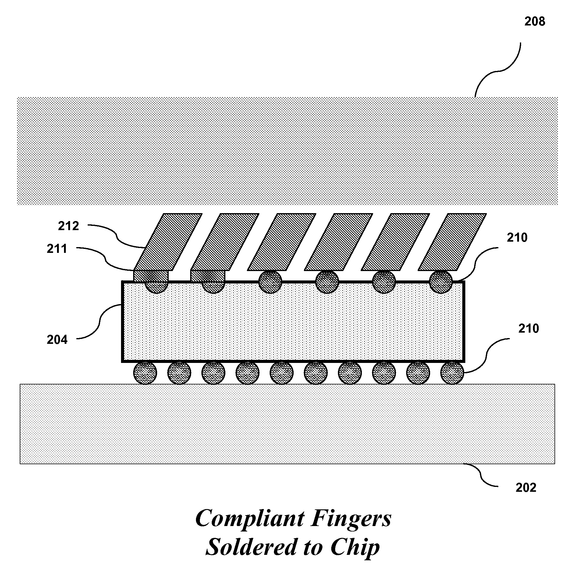
[0024]We describe a novel, low-cost heat sink structure which provides compliance in all directions while maintaining a gap of substantially zero between the chip and heat spreader. Compliance is achieved through the use of angled beams.

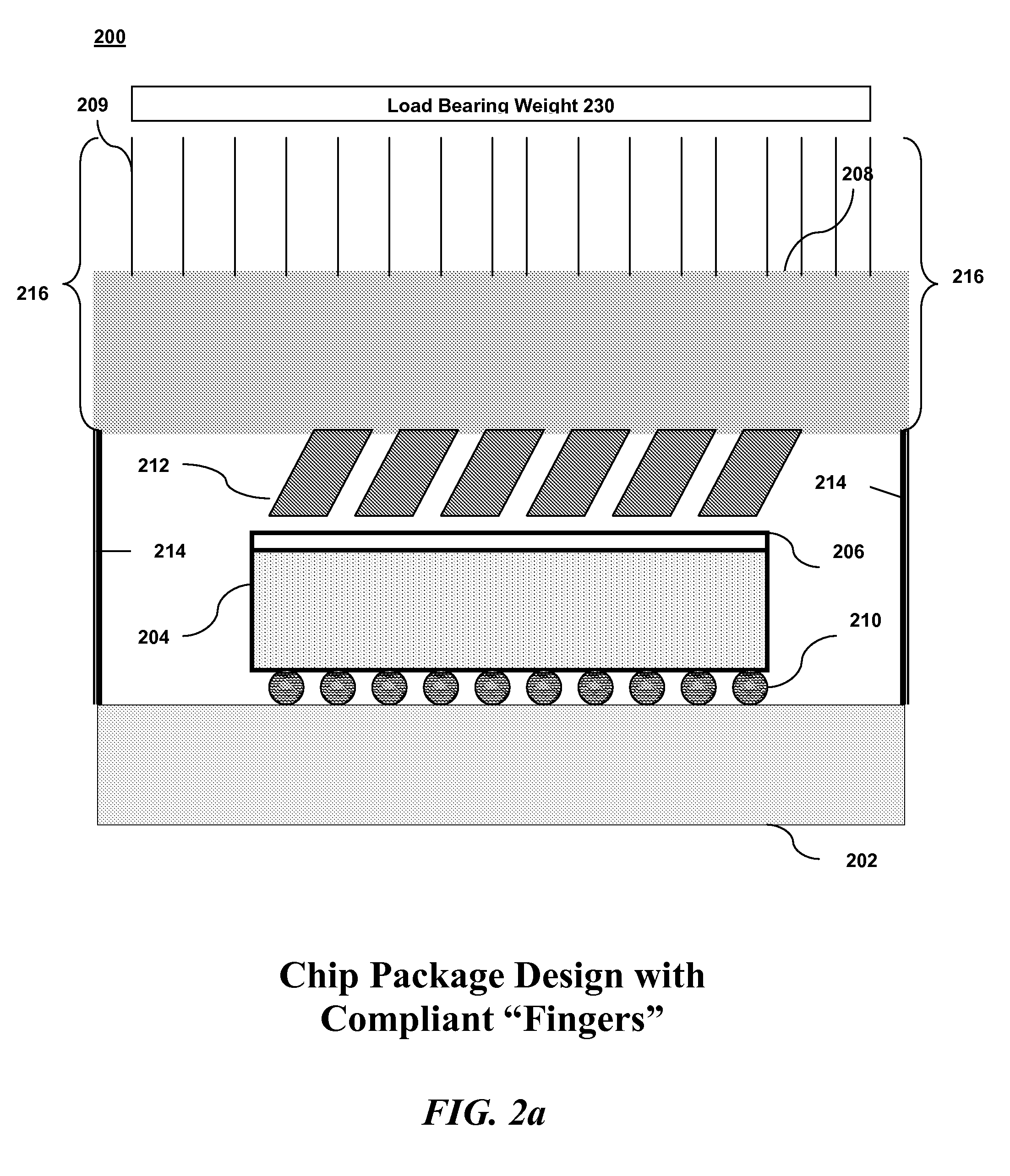
[0025]Referring now in specific detail to the drawings, and particularly FIG. 2, there is illustrated a block diagram of a chip package with compliant “fingers”212 according to an embodiment of the invention. To create the fingers a copper alloy or other high conductivity material block is machined to produce compliant “fingers” which contact the chip. The fingers 212 are machined such that they make contact with the chip at an angle relative to the chip surface, providing compliant beams which are able to bend in response to changes in the relative position of the chip 204 to the heat spreader 208 in the X, Y, and Z directions. The fingers 212 may be fabricated by cutting a solid copper alloy block at an angle in an X-Y pattern to a predetermined de...


PUM


Abstract

A heat dissipating structure includes: a heat spreader; and a plurality of compliant beams attached to the heat spreader. The beams are formed of a high-conductive material such that a maximum stress of each beam is less than a fatigue stress of the high-conductive material; said beams are placed at an angle relative to a chip surface such that the beams are able to exert bending compliance in response to x, y, and z forces exerted upon them. The structure also includes a thermal material interface for bonding said structure to the chip surface. Both the heat spreader and the compliant beams can be machined from a copper block. An alternative heat dissipating structure includes compliant beams soldered to the chip surface.

Description

CROSS-REFERENCE TO RELATED APPLICATIONS[0001]Not Applicable.STATEMENT REGARDING FEDERALLY SPONSORED-RESEARCH OR DEVELOPMENT[0002]Not Applicable.INCORPORATION BY REFERENCE OF MATERIAL SUBMITTED ON A COMPACT DISC[0003]Not Applicable.FIELD OF THE INVENTION[0004]The invention disclosed broadly relates to the field of cooling devices for microelectronic devices, and more particularly relates to the field of compliant thermal heat sinks.BACKGROUND OF THE INVENTION[0005]A heat sink is a device that is attached to a microprocessor chip to keep it from overheating by conducting the heat generated from the chip to the ambient environment which may be air or a liquid coolant. Basic heat sink structures include a heat spreader which makes thermal contact with the silicon chip via an interface of a thermally conductive adhesive and a set of fins which provide for conduction of the heat from the chip to the ambient environment. The purpose of the heat spreader is to provide good thermal conductio...

Claims


Application Information

Patent Timeline
IPC IPC(8): H05K7/20H01L21/00H01L23/10
CPCH01L23/3677H01L23/433H01L2224/16H01L2924/01004H01L2924/10253H01L2924/00
Inventor CHAINER, TIMOTHY J.
Owner GLOBALFOUNDRIES US INC
Why Eureka
Try Eureka