
Removing effects of near surface geology from surface-to-borehole electromagnetic data

a technology of electromagnetic data and surface geology, applied in the field of geophysical data acquisition and processing, can solve the problems of discontinuous, complex geology near the earth's surface, and inapplicability to the surface-deployed transmitter

Active Publication Date: 2009-02-12
SCHLUMBERGER TECH CORP
View PDF5 Cites 49 Cited by
  • Summary
  • Abstract
  • Description
  • Claims
  • Application Information

AI Technical Summary

Benefits of technology

[0006]One embodiment of the invention involves a method that includes developing an electromagnetic property model of a near surface area and using this electromagnetic property model and electromagnetic data acquired using one or more electromagnetic transmitters located above the near surface area and one or more electromagnetic receivers located within a wellbore to determine one or more electromagnetic properties of a subsurface area. Another embodiment of the invention involves an electromagnetic data acquisition system that includes one or more

Problems solved by technology

881-931, in Electromagnetic Methods in Applied Geophysics edited by G. R. Hohman, but he limits his discussion in this text to exploration for metallic ores using simple models and does not apply the technology for subsurface formation imaging.
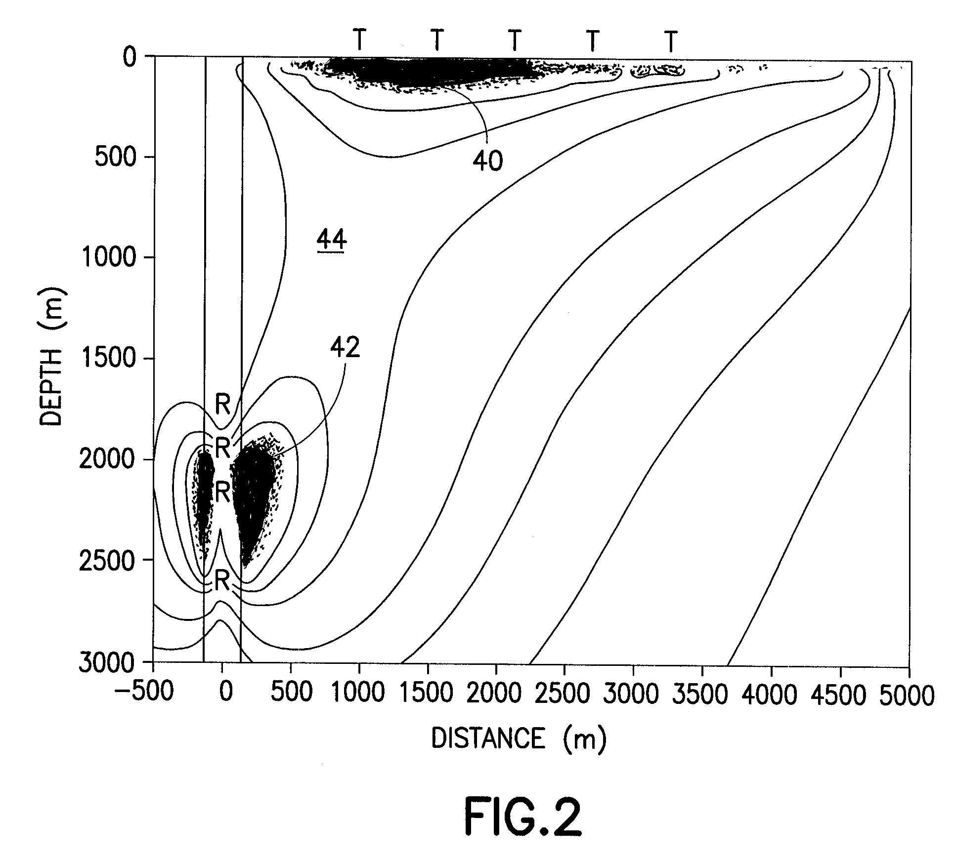
Whereas a high sensitivity is desired near the borehole-deployed receiver array to map the formation resistivity, it is not useful near the surface-deployed transmitter.
In addition, the geology near the earth's surface tends to be complex and discontinuous.
This problem is analogous to the statics issue faced in surface seismics, where the local conditions can statically shift the formation response from the expected state.

Method used


Image

  • Removing effects of near surface geology from surface-to-borehole electromagnetic data
  • Removing effects of near surface geology from surface-to-borehole electromagnetic data
  • Removing effects of near surface geology from surface-to-borehole electromagnetic data

Examples


Embodiment Construction

Overview

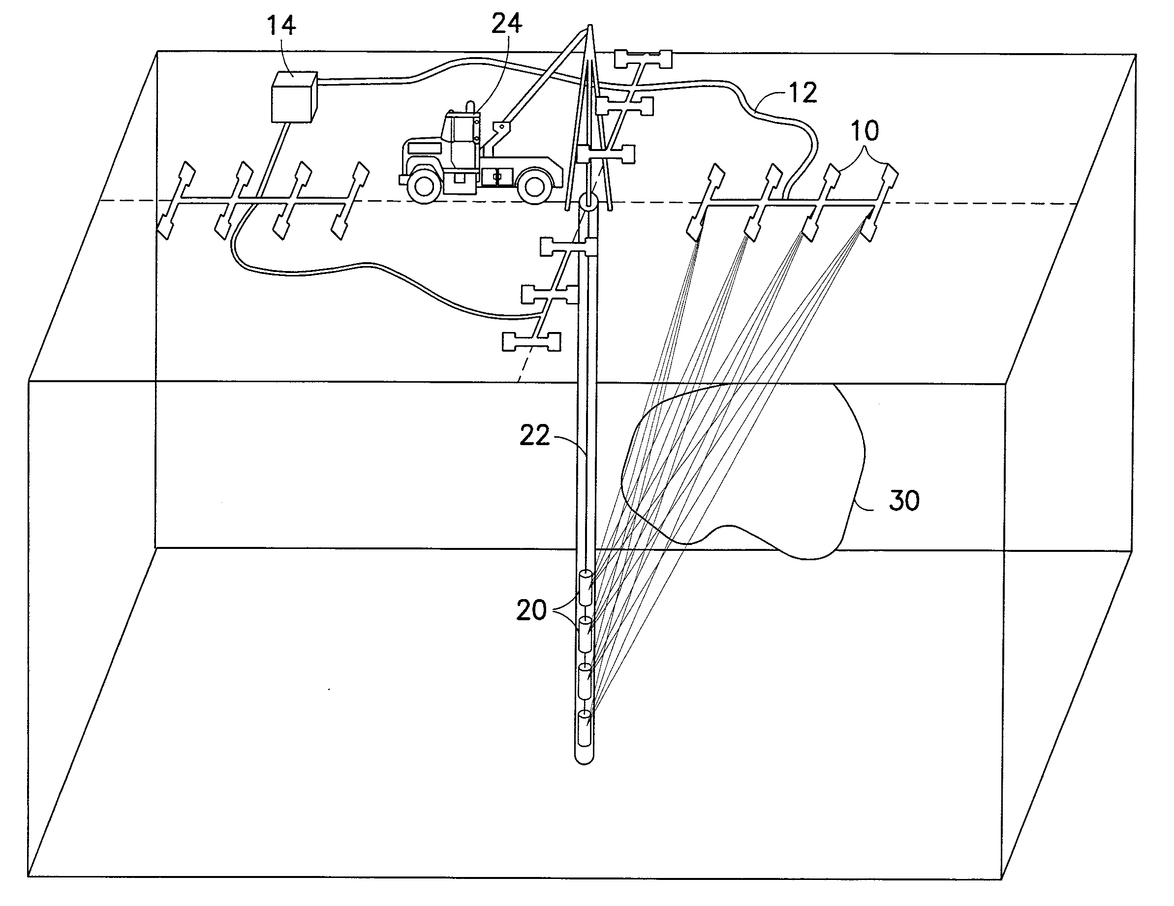
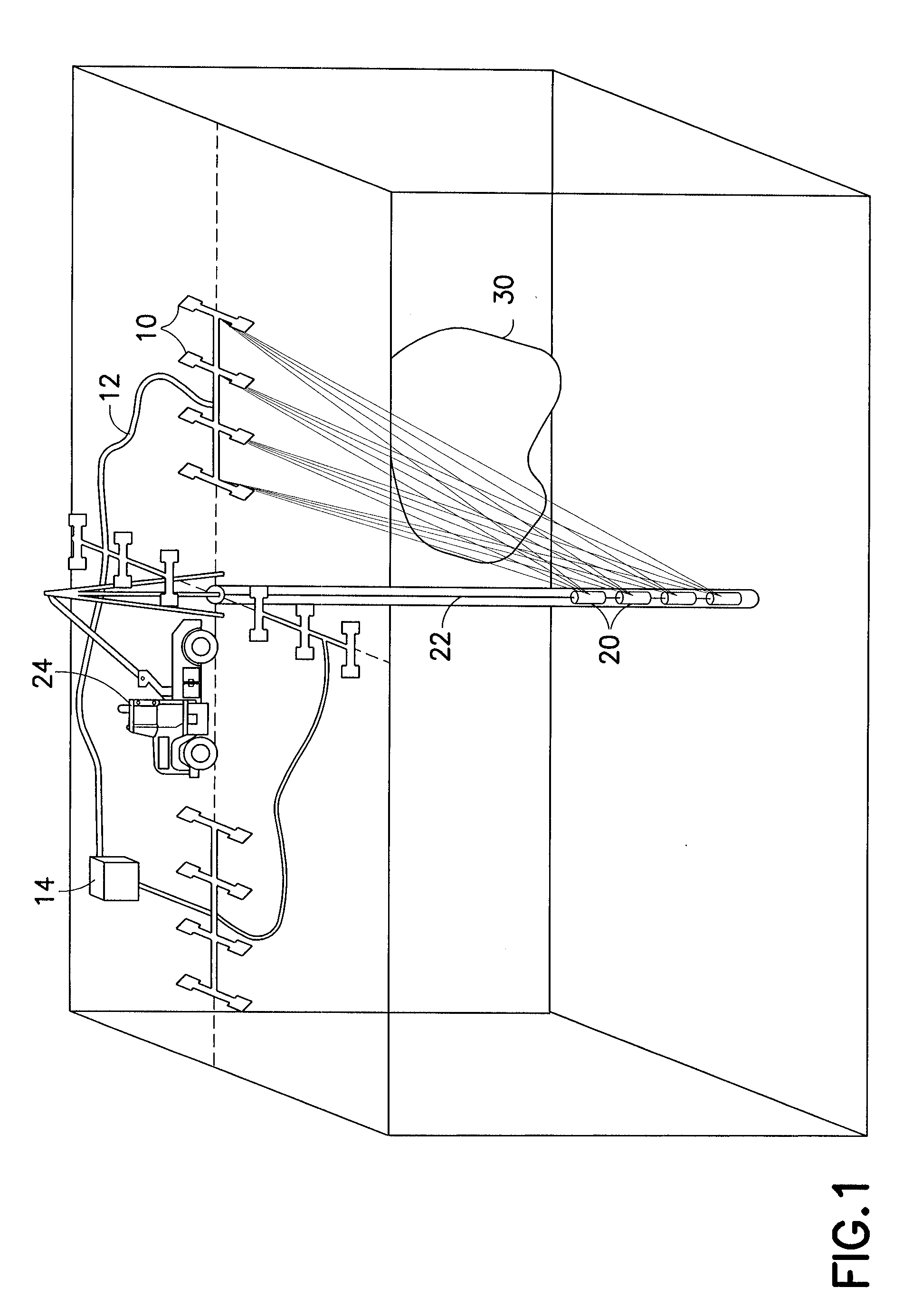
[0011]This invention pertains to the acquisition and processing of surface to borehole (STB) electromagnetic data, typically acquired with a series of sources (also referred to as transmitters) deployed on the surface of the earth in concert with an array of borehole receivers (sometimes referred to herein as the “first” receivers) to image the subsurface away from the receiver locations within the well, often to offsets of 20-1500 meters away from the borehole, and also pertains to equipment that may be used to acquire such data.

[0012]This invention allows the separation of the electromagnetic effects (typically resistivity, but other electromagnetic properties such as conductance or permittivity may be determined as well) of the near surface geology from the deep resistivity distribution or related electromagnetic properties of the subsurface area that are sought. In one embodiment of the inventive method, we propose that this separation occurs in a three step process that...


PUM


Abstract

A method that involves developing an electromagnetic property model of a near surface area and using this electromagnetic property model and electromagnetic data acquired using one or more electromagnetic transmitters located above the near surface area and one or more electromagnetic receivers located within a wellbore to determine one or more electromagnetic properties of a subsurface area. Also an electromagnetic data acquisition system that includes one or more electromagnetic transmitters capable of being operated on the earth's surface, one or more first electromagnetic receivers capable of being operated within a wellbore and capable of receiving signals from the one or more electromagnetic transmitters, and one or more second electromagnetic receivers capable of being located on the earth's surface near the one or more electromagnetic transmitters and capable of receiving signals from the one or more electromagnetic transmitters. Related embodiments are also described.

Description

FIELD OF THE INVENTION[0001]This invention is generally related to geophysical data acquisition and processing, and more particularly to methods of acquiring, processing, and / or using surface-to-borehole electromagnetic data and associated surface-to-borehole electromagnetic data acquisition systems.BACKGROUND[0002]Surface based electromagnetic (EM) data acquisition is well described in the geophysical literature in published papers and books. The types of EM data acquisition configurations considered below are described in texts such as Kaufman, A. A., and Keller, G. V., 1983, “Frequency and Transient Electromagnetic Sounding”, published by Elsevier and Hohman, G. R., 1991, “Electromagnetic Methods in Applied Geophysics”, published by the Society of Exploration Geophysicists.[0003]Surface-to-borehole EM data acquisition is described in Dyck, A., 1991, “Drill-Hole Electromagnetic Methods”, pp. 881-931, in Electromagnetic Methods in Applied Geophysics edited by G. R. Hohman, but he l...

Claims


Application Information

Patent Timeline
IPC IPC(8): G01V3/12E21B47/00G01V3/18
CPCG01V3/30
Inventor WILT, MICHAELKRAMER, GARRETT
Owner SCHLUMBERGER TECH CORP
Learn More