Apparatus for estimating state of vehicle located in frontward field

Inactive Publication Date: 2009-02-12
DENSO CORP
View PDF31 Cites 46 Cited by
  • Summary
  • Abstract
  • Description
  • Claims
  • Application Information

AI Technical Summary

Benefits of technology

[0013]In this way, the non-linear motion model is used, while the conventional estimation apparatus employs a liner motion model for estimating the vehicle state. Hence, in the present invention, the vehicle state including the an

Problems solved by technology

However, the above-described estimation apparatus is confronted with two difficulties.
One difficult is that it is difficult to accurately detect information indicative of the size and direction of a vehicle located in the frontward field (hereinafter, simply referred to as “located ahead”).
Since the shape of a ve

Method used


Image

  • Apparatus for estimating state of vehicle located in frontward field
  • Apparatus for estimating state of vehicle located in frontward field
  • Apparatus for estimating state of vehicle located in frontward field

Examples


Embodiment Construction

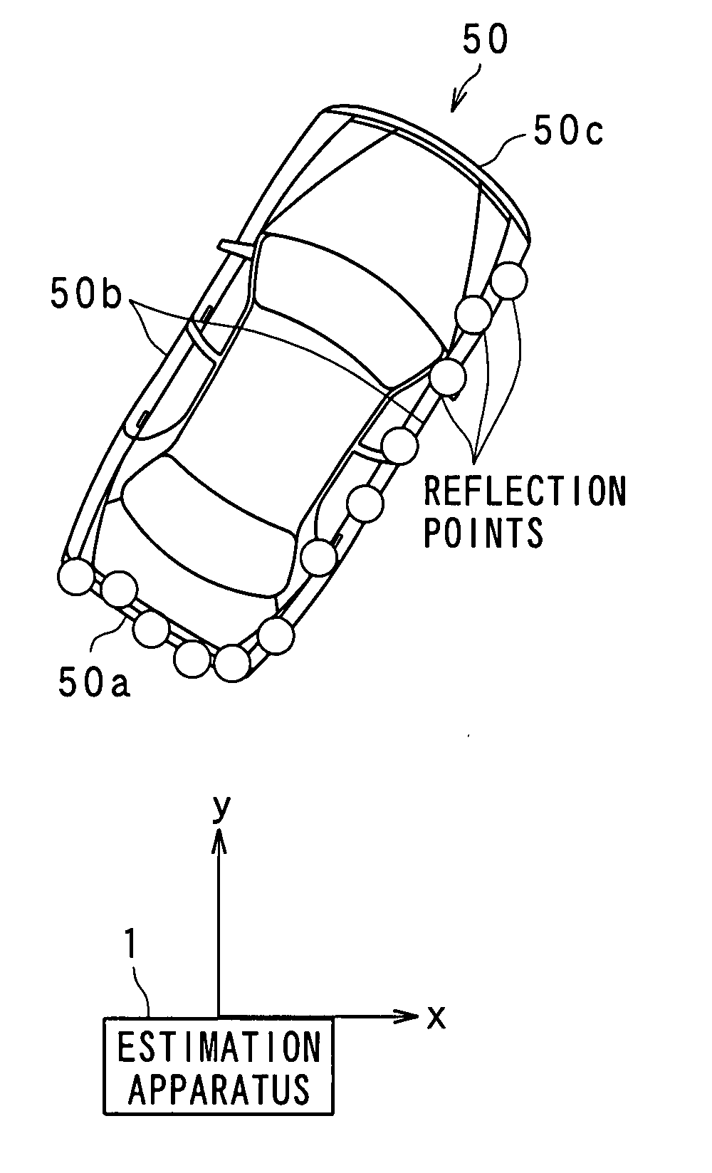
[0032]Referring to FIGS. 1-17, an estimation apparatus according to a first embodiment of the present invention will now be described.

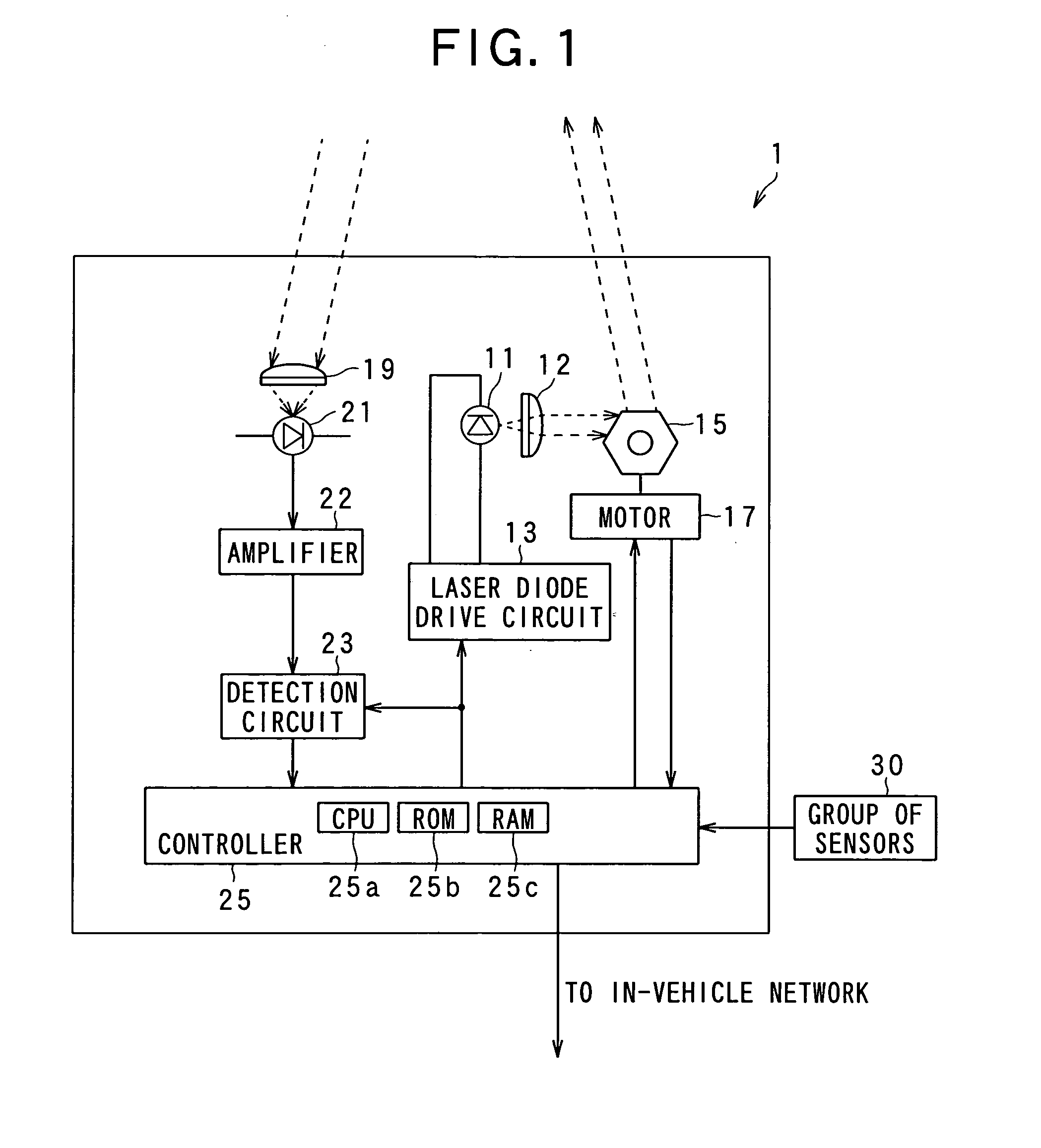
[0033]FIG. 1 outlines in a block form the entire configuration of an estimation apparatus 1 according to the first embodiment of the present invention. The present estimation apparatus 1 is mounted in a front part of a four-wheel vehicle.

[0034]The estimation apparatus 1 according to the present embodiment is provided, as shown in FIG. 1, a laser diode 11 emitting laser light and a collimating lens 12 producing the laser light emitted from the laser diode 11 into parallel light, in addition to a laser diode drive circuit 13, a mirror 15, a motor 17, a converging lens 19, a photodiode 21, an amplifier 22, a detection circuit 23, and a controller 25. The laser diode drive circuit 13 is configured to drive the laser diode 11 by applying drive power thereto. The mirror 15 reflects the laser light emitted from the laser diode 11. The motor 17 is configured ...


PUM


Abstract

An estimation apparatus estimates a state of a vehicle located in a frontward field. Positional coordinates of a plurality of positions on an object are measured by radiating radar waves toward the frontward field and receiving reflected radar waves from an object in the frontward field. A position, direction and size of a graphical pattern are obtained by approximating the graphical pattern into a profile pattern of the object. The graphical pattern is modeled as a profile of a vehicle. A direction and size of the graphical pattern are unknown. The profile pattern is expressed by the positional coordinates. As the state of the vehicle located ahead, a position of the vehicle, a direction of the vehicle, and one of a whole length and a whole width of the vehicle are estimated based on the position, the direction, and the size of the graphical pattern.

Description

CROSS REFERENCES TO RELATED APPLICATIONS[0001]The present application relates to and incorporates by reference Japanese Patent Application No. 2007-210275 filed on Aug. 10, 2007BACKGROUND OF THE INVENTION[0002]1. Field of the Invention[0003]The present invention relates to an estimation apparatus for estimating the state of a vehicle located in a frontward field, and in particular, the estimation apparatus which involves, for the estimation, the transmission of radar waves toward a field and the reception of radar waves reflected from objects, such as vehicles, located in the field.[0004]2. Description of the Related Art[0005]Recently, various countermeasures for driving safely have been provided. One such countermeasure is to estimate the travel states of vehicles which are located ahead. Japanese Patent Laid-open Publication No. 2002-99986 discloses an apparatus which is able to provide such countermeasures. This publication provides a radar apparatus that uses radar waves to esti...

Claims


Application Information

Patent Timeline
IPC IPC(8): G01S13/00G01S17/89G01S17/931
CPCG01S7/487G01S17/936G01S17/89G01S17/931
Inventor OGAWA, TAKASHI
Owner DENSO CORP
Why Eureka
Try Eureka