
Compensation Element Adjustment Mechanism and Projector

a technology of compensating element and adjustment mechanism, which is applied in the direction of optics, projectors, instruments, etc., can solve the problems of difficult precision difficult to perform fine adjustment of the mounting posture of the optical compensation sheet, and difficult fixation thereafter, so as to achieve simple structure, improve the contrast of image display, and improve the effect of simple structur

Inactive Publication Date: 2009-02-12
SEIKO EPSON CORP
View PDF4 Cites 12 Cited by
  • Summary
  • Abstract
  • Description
  • Claims
  • Application Information

AI Technical Summary

Benefits of technology

[0006]An advantage of some aspects of the invention is to provide a compensation element adjustment mechanism with which the fine adjustment of the mounting posture of the optical compensation element can easily be performed, and a projector having such a compensation element adjustment mechanism incorporated therein.
[0008]In the compensation element adjustment mechanism described above, since the frame supporting the optical compensation element has a pair of shaft members disposed at positions opposed to each other in the periphery of the optical compensation element, the mounting posture of the frame, namely of the optical compensation element can be adjusted with respect to the light modulation device or the like. On this occasion, since the fixing section restricts the displacement of the frame with respect to the support holder with an elastic contact, the posture of the optical compensation element can be changed as much as a desired amount together with the frame, and held as it stands, thus the precise adjustment of the mounting posture of the optical compensation element and the simple fixing thereof after the adjustment become possible.
[0010]According to another aspect of the invention, the fixing section includes a first member attached to the support holder and a second member extending from the frame, and restricts the displacement of the frame to the support holder by an elastic contact between the first and second members. In this case, simple fixation of the mounting posture of the optical compensation element becomes possible by interposition of the first member.
[0011]According to still another aspect of the invention, an operating knob capable of adjusting the posture of the frame is provided by extending the second member outside the support holder. In this case, simple posture adjustment of the frame, namely the optical compensation element becomes possible by using the operating knob.
[0014]According to still another aspect of the invention, the pair of shaft members is rod-like members or elongated members respectively supported by a pair of slit-like notches provided to the support holder. In this case, simple support and smooth posture adjustment of the frame, namely the optical compensation element becomes possible.
[0018]In the projector described above, the illumination light of the respective colors enters the light modulation device of the respective colors to be modulated by the light modulation device of the respective colors into the light beams of the respective colors, and then the light beams of the respective colors are combined by the light combining member, and the combined light beam is projected on the screen as an image via the projection optical system. On this occasion, since the compensation element adjustment mechanism according to the aspects of the invention with a simple structure as described above is used, the optical compensation element can precisely be arranged with a simple structure, thus the contrast in image display can easily be improved.

Problems solved by technology

However, in the holder described above, it is difficult to perform a fine adjustment of the mounting posture of the optical compensation sheet.
Specifically, an operation of fixing the posture of the frame member with a screw is absolutely necessary after adjusting the posture of the frame member, and the posture of the frame member can easily be changed again when fixing it with a screw after the adjustment of the frame member, thus the precise adjustment of the mounting posture of the optical compensation sheet and the fixation thereafter are difficult.

Method used


Image

  • Compensation Element Adjustment Mechanism and Projector
  • Compensation Element Adjustment Mechanism and Projector
  • Compensation Element Adjustment Mechanism and Projector

Examples


first embodiment

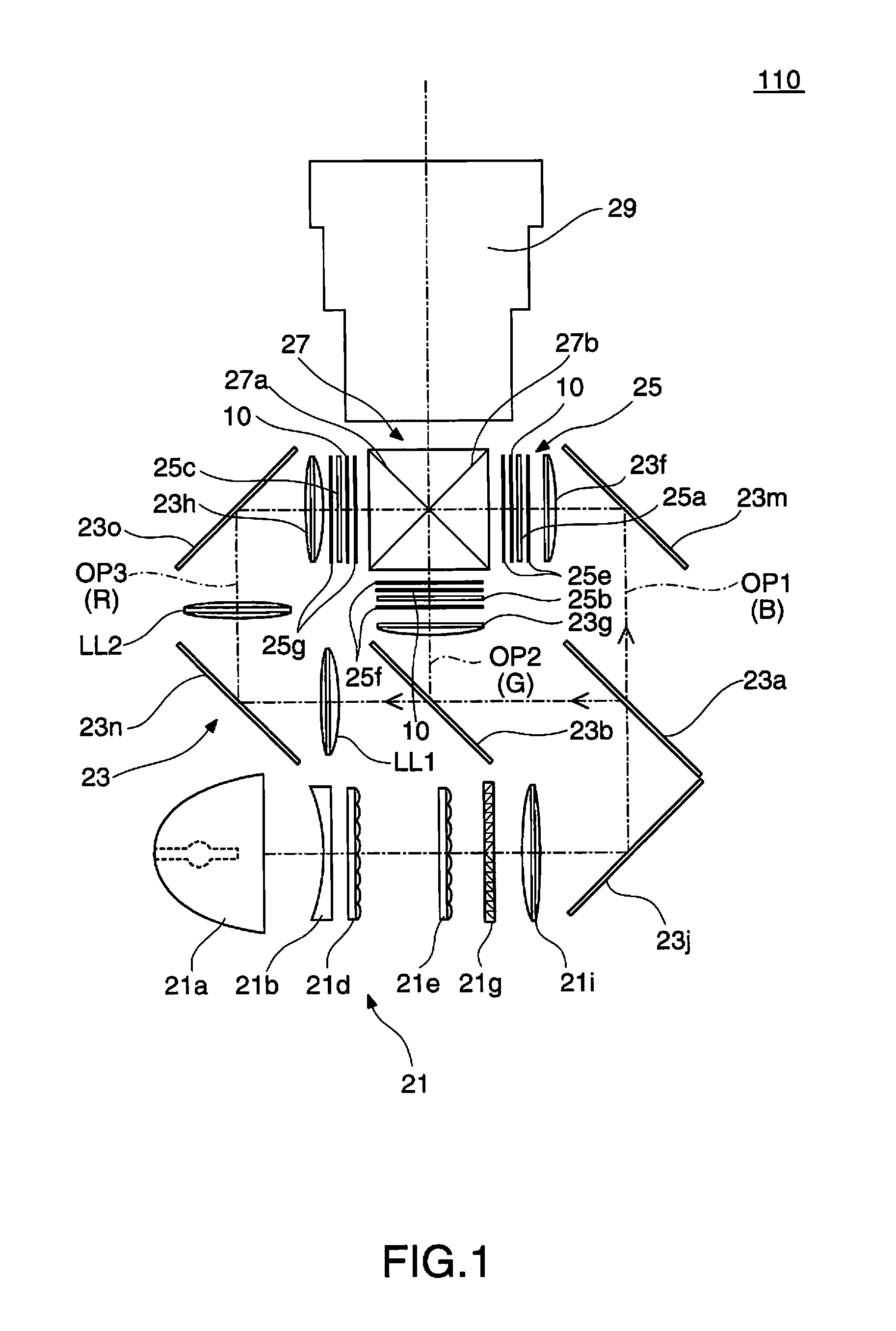
[0030]FIG. 1 is a diagram for explaining a structure of a projector according to a first embodiment of the invention. The present projector 110 is provided with a light source device 21 for generating source light, a color separation optical system 23 for separating the source light from the light source device 21 into three colors of light, red, green, and yellow, a light modulation section 25 illuminated by the illumination light of respective colors emitted from the color separation optical system 23, a cross dichroic prism 27 for combining image light of respective colors from the light modulation section 25, and a projection lens 29 as a projection optical system for projecting the image light passing through the cross dichroic prism 27 on a screen (not shown).

[0031]In the projector 110 described above, the light source 21 is provided with a light source lamp 21a, a concave lens 21b, a pair of fly-eye lenses 21d, 21e, a polarization conversion member 21g, and an overlapping len...

second embodiment

[0052]A compensation element adjustment mechanism of a second embodiment will hereinafter be explained. It should be noted that the compensation element adjustment mechanism, namely the emission filter unit of the second embodiment is obtained by modifying the emission filter unit 125b of the first embodiment shown in FIGS. 3A, 3B and so on, and only different parts will be explained below.

[0053]FIG. 8A is a perspective view of the emission filter unit 225b in the second embodiment, and FIG. 8B is a front view of a frame 231 of the emission filter unit 225b.

[0054]In this case, the emission filter unit 225b is provided with the frame 231 instead of the frame 31 shown in FIG. 4B and so on. The frame 231 has a circular plate shape, and is provided with a main body section 231a for supporting the optical compensation element 210, a pair of shaft members 231b, 231c obliquely extending outward, and a lever member 231e extending upward from an upper center thereof. Here, the main body sec...

third embodiment

[0056]A compensation element adjustment mechanism of a third embodiment will hereinafter be explained. It should be noted that the compensation element adjustment mechanism, namely the emission filter unit of the third embodiment is obtained by modifying the emission filter unit 125b of the first embodiment shown in FIGS. 3A, 3B and so on, and only different parts will be explained below.

[0057]FIGS. 10A through 10C are diagrams for explaining an emission filter unit 325b and so on of the third embodiment, wherein FIG. 10A is a bottom view of the emission filter unit 325b, and FIGS. 10B and 10C are side views for explaining an arrangement of a frame 331 forming the emission filter unit 325b shown in FIG. 10A.

[0058]In this case, a current plate 331k is disposed at a lower end of the frame 331. The emission filter unit 325b is cooled by a cooling airflow CW supplied from an air-cooling device, not shown, and the cooling airflow CW flows from the lower side to the upper side. Here, in t...


PUM


Abstract

A compensation element adjustment mechanism used with a light modulation device and a polarization plate includes: an optical compensation element disposed between the light modulation device and a polarization plate; a frame for supporting the optical compensation element, and having a pair of shaft members disposed at positions opposed to each other on a periphery of the optical compensation element; a support holder to be fixed with respect to the light modulation device, and for rotatably supporting the pair of shaft members; and a fixing section for restricting a displacement of the frame to the support holder by an elastic contact.

Description

BACKGROUND[0001]1. Technical Field[0002]The present invention relates to a compensation element adjustment mechanism for optical compensation of a light modulation device, and a projector having such a compensation element adjustment mechanism incorporated therein.[0003]2. Related Art[0004]An optical compensation sheet is disposed on an entrance side or an emission side of a liquid crystal panel in an optical device for image light formation incorporated in a projector, and in order for adjusting the mounting posture of the optical compensation sheet, there is used a holder capable of rotating the optical compensation sheet around the optical axis or making the optical compensation sheet turn around the rotational axis perpendicular to the optical axis (see JP-A-2007-78735 (Patent Document 1)). In the case, for example, in which the optical compensation sheet is made turn around the rotational axis perpendicular to the optical axis together with a frame member, a pair of shaft membe...

Claims


Application Information

Patent Timeline
IPC IPC(8): G02F1/13363G03B21/14
CPCG03B21/14G03B21/16G03B21/2073
Inventor UTAGAWA, TAKESHI
Owner SEIKO EPSON CORP
Learn More