
Power inverter

a power inverter and power technology, applied in the direction of solid-state devices, semiconductor devices, electrical apparatus construction details, etc., can solve the problems of reducing the size of the power inverter, reducing the heat value and reducing the accuracy of control, and equipment tend to get bigger

Active Publication Date: 2009-02-12
HITACHI ASTEMO LTD
View PDF16 Cites 87 Cited by
  • Summary
  • Abstract
  • Description
  • Claims
  • Application Information

AI Technical Summary

Benefits of technology

[0013]As electric energy converted by the power inverter increases, equipments tend to get bigger. So, it is preferable to minimize the volume of the equipments regardless of increase in the electric energy, in other words, for example, to increase the value of maximum convertible electric power per unit volume of the power inverter. For that, it is desirable to achieve a balance between low inductance and reduction in the size. Here, reduction in the size refers to maximization of the value of maximum convertible electric power per unit volume of the power inverter.

Problems solved by technology

However, to extremely lengthen intervals between the switching operations for the switching device may reduce the accuracy of control.
The patent document 2, however, has a challenge in reducing the heat value and reducing the size of the power inverter because the power inverter, particularly the in-car power inverter, does not have enough space around it.
As electric energy converted by the power inverter increases, equipments tend to get bigger.

Method used


Image

  • Power inverter
  • Power inverter
  • Power inverter

Examples


Embodiment Construction

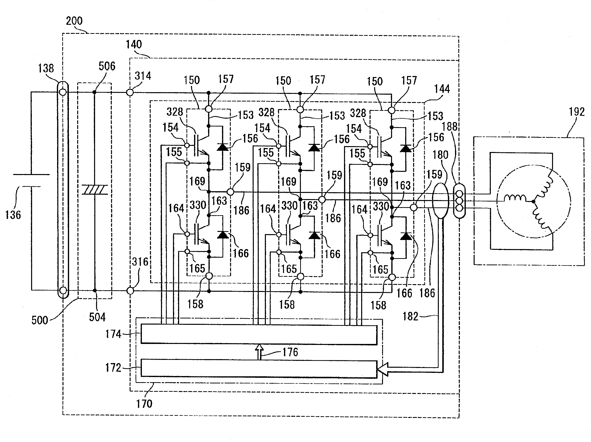
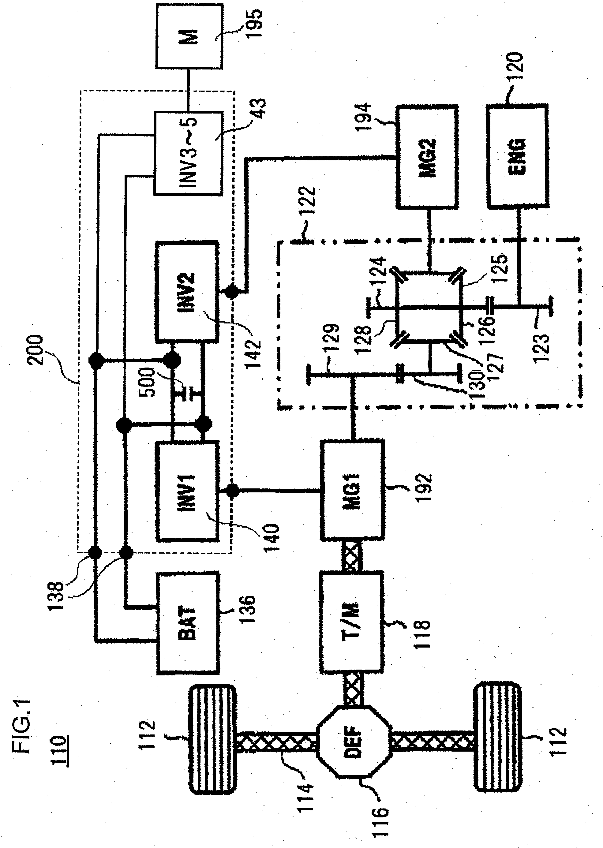
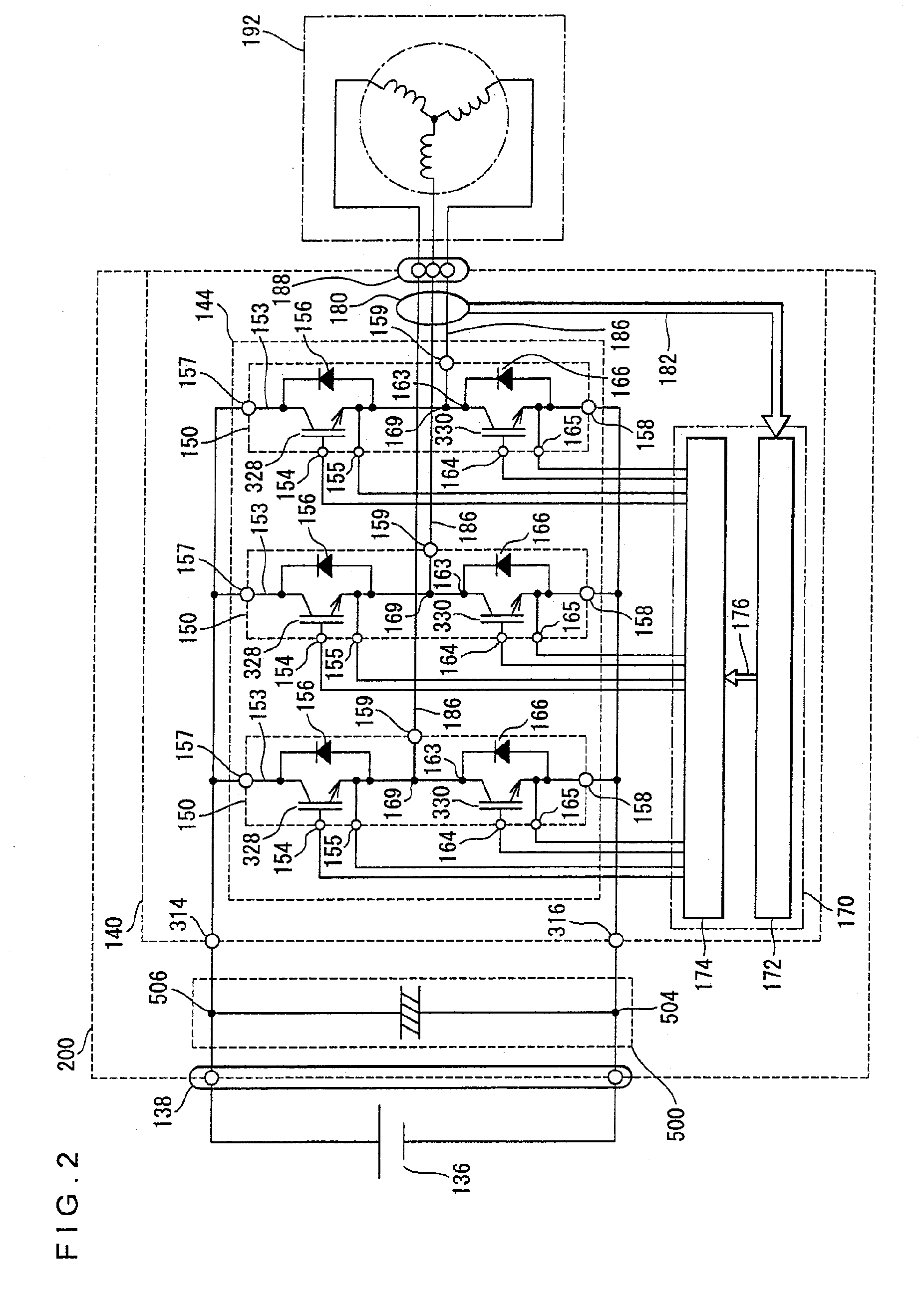
[0055]A power inverter in accordance with embodiments of the present invention will be hereinafter described with reference to the drawings. Technical problems to be improved or solved and technologies for solving the problems will be described first, with regard to the power inverter in accordance with the present embodiment.

[0056][Reduction in Inductance]

[0057]There are three measures to take for reducing inductance of electrical circuits: firstly, reduction in inductance of a power module; secondly, reduction in inductance of a capacitor module; and thirdly, reduction in inductance of a connection circuit between the power module and the capacitor module. It is most preferable to implement all the three measures. However, implementing one of the three has effect. Implementing two of the three has more preferable effect than implementing one of the three has.

[0058]The first measure, reduction in inductance of the power module, will be described as follows. Semiconductor device chi...


PUM


Abstract

In a power inverter, a coolant passage is fixed to a chassis to cool the chassis; the chassis is divided into a first region and a second region by providing the coolant passage in the chassis; a power module is provided in the first region as fixed to the coolant passage; a capacitor module is provided in the second region; and the DC terminal of the capacitor module is directly connected to the DC terminal of the power module.

Description

INCORPORATION BY REFERENCE[0001]The disclosure of the following priority application is herein incorporated by reference:[0002]Japanese Patent Application No. 2007-208505 filed Aug. 9, 2007BACKGROUND OF THE INVENTION[0003]1. Field of the Invention[0004]The present invention relates to a power inverter that converts Direct Current (DC) power into Alternate Current (AC) power and vice versa.[0005]2. Description of Related Art[0006]The power inverter includes a function with which DC power supplied from a DC power supply is converted into AC power to be supplied to an AC electricity load such as an electric rotating machine, and a function with which AC power generated by an electric rotating machine is converted into DC power to be supplied to a DC power supply. To perform the conversion function, the power inverter further includes an inverter circuit which includes a switching device, and by repeating conduction operation and interrupt operation with the switching device, the power ...

Claims


Application Information

Patent Timeline
IPC IPC(8): H05K7/20
CPCH02M7/003H02M7/5387H02M7/219H05K7/20927H01L2224/48091H01L2224/48137H01L2924/1305H01L2924/13055H01L2924/13091H01L2924/19107H01L2924/00014H01L2924/00
Inventor NISHIKIMI, FUSANORINAKATSU, KINYA
Owner HITACHI ASTEMO LTD
Learn More