Method and Apparatus for Sintering of Inorganic Materials as Well as Resulting Objects

a technology of inorganic materials and sintering methods, applied in metal-working apparatuses, heat inorganic powder coatings, metallic material coating processes, etc., can solve the problems of low objectivity, time-consuming fabrication methods, and low objectivity of this method, and achieve the effect of higher objectivity

Inactive Publication Date: 2009-02-12
MBN NANOMATERIALIA +1
View PDF8 Cites 53 Cited by
  • Summary
  • Abstract
  • Description
  • Claims
  • Application Information

AI Technical Summary

Benefits of technology

[0006]It is a main aim of the present invention a sintering system which is more ef

Problems solved by technology

This fabrication method is time consuming, thus of a low objectivity, in consideration of the alternate operation of the powder depositing means and of the the laser beam.
For the functional similarity with the above discussed system the obj

Method used


Image

  • Method and Apparatus for Sintering of Inorganic Materials as Well as Resulting Objects
  • Method and Apparatus for Sintering of Inorganic Materials as Well as Resulting Objects
  • Method and Apparatus for Sintering of Inorganic Materials as Well as Resulting Objects

Examples


Embodiment Construction

[0016]As already discussed in the preceding paragraphs the invention refers to the fabrication of tridimensional solid objects which makes use as a raw material of a powder, consisting of particles of one or more inorganic materials (phases) like metals, alloys, ceramics, carbon, carbides etc. The powder is preferably multi-phase so that one phase does not exceed 85% in volume while the sum of the other phases is at least 15% in volume and has a melting temperature below 80% of the melting temperature in ° C. of the first phase.

[0017]Many other examples of usable powder could be mentioned and are accessible from the metallurgical literature such as:

First phaseSecond phaseMelting temp.MeltingMetal or alloy[° C.]Metal or alloytemp. [° C.]Fe1535FeP (10 wt % P) alloy1050 Fe1535FeC (4.2 wt % C)1150 alloyTi1670Sn230Cu1083Sn230Cu1083Zn420Fe1535FeCu alloy1083 ÷ 1535(+)Ti1670Ti—Sn alloy 230 ÷ 1670(+)Legenda:(+)= temperature depending on the actual compositionof the alloy.

[0018]Powders consis...


PUM

PropertyMeasurementUnit
Fractionaaaaaaaaaa
Angleaaaaaaaaaa
Fractionaaaaaaaaaa

Abstract

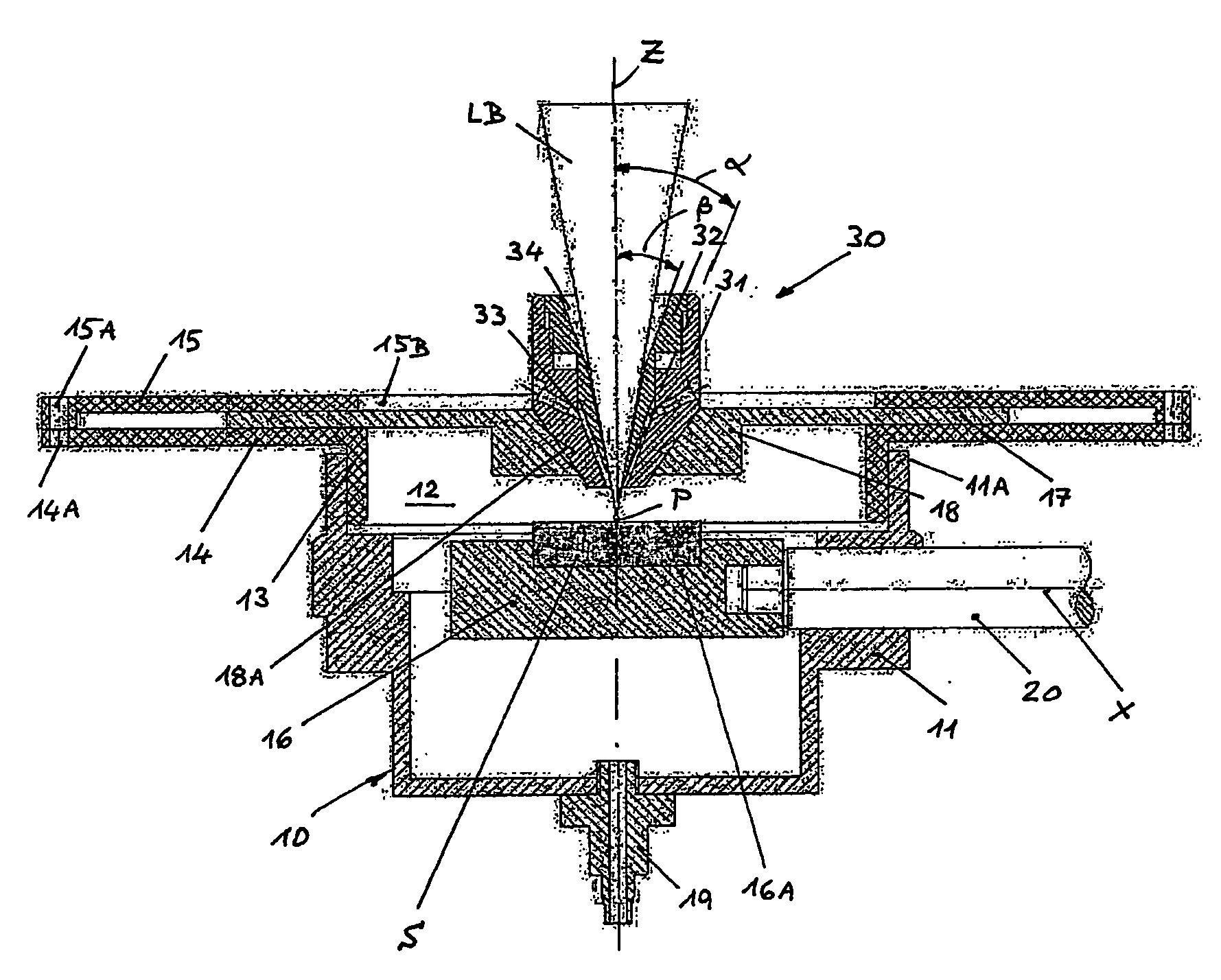
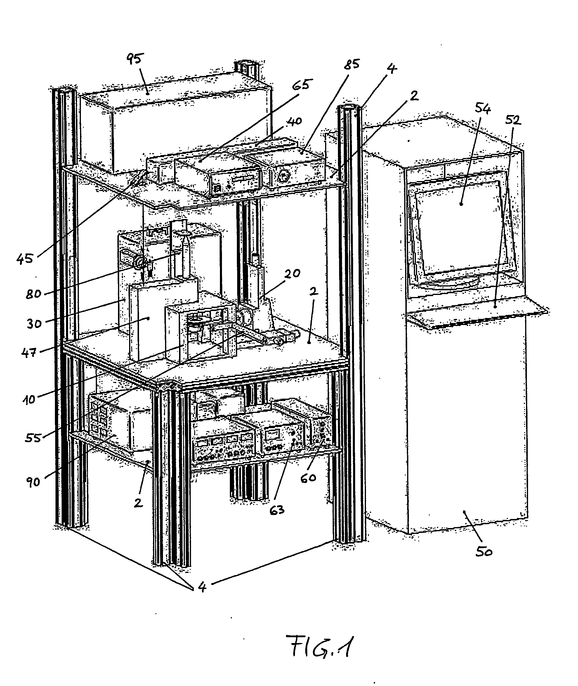
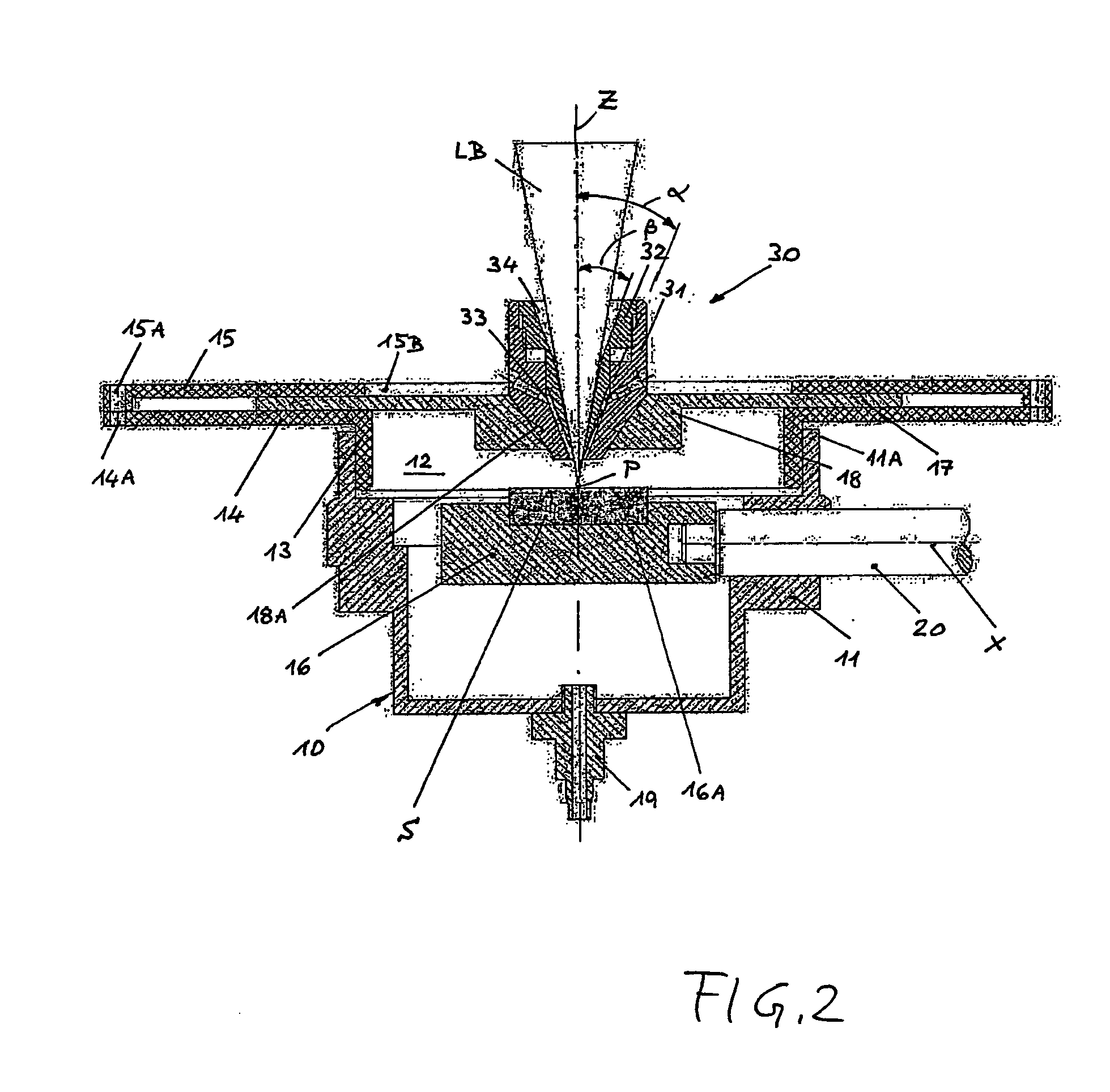
The invention refers to a method and an apparatus for fabricating a tridimensional solid object by sintering inorganic particles of controlled size distribution. The particles are directed onto a target area in a powdery stream in the shape of a conical surface which is coaxial to a simultaneous heating flux while an at least bidimensional relative movement is maintained between the target area, the powdery stream and the heating flux. As a result the particles sinterization occurs in a single operation directly onto the target area. The resulting tridimensional solid objects are also claimed.

Description

FIELD OF THE INVENTION[0001]The present invention refers to the fabrication of tridimensional solid objects from at least one inorganic material such as metals, alloys, ceramics, carbides, etc. in form of powder and to the resulting objects.DESCRIPTION OF THE RELATED ART[0002]The so-called laser sintering technique is known in particular through the disclosure made by quite a number of documents, including the following.[0003]In the U.S. Pat. No. 4,863,538 assigned to the University of Texas it is envisaged to build up a object by depositing a powdery material in successive layers which are independently sintered by a laser beam, soon after their deposition on a target area on a target area of a predetermined cross-section. The cross-section of a chosen diameter of laser beam is scanned over each layer and the beam is switched on to sinter only the powder lying within the predetermined cross-section under a control by computer means. This fabrication method is time consuming, thus o...

Claims


Application Information

Patent Timeline
IPC IPC(8): B32B15/02B22F3/105B22F3/00B23K26/34C23C4/12C23C4/18C23C24/08
CPCB22F3/008Y10T428/12014B22F2998/00B22F2998/10B22F2999/00B23K26/34C23C4/12C23C4/185C23C24/08B22F3/1055B23K35/0244B23K26/3273B23K26/3266B23K26/3206B22F2003/1056B22F1/0014B22F3/15B22F3/004B22F2202/01B23K26/32B23K2103/50B23K2103/52Y02P10/25B22F12/41B22F10/25B22F12/53
Inventor MATTEAZZI, PAOLOBECKER, HINRICH
Owner MBN NANOMATERIALIA
Why Eureka
Try Eureka