Flashback blood collection needle

a blood collection needle and flashback technology, applied in medical science, packaging, diagnostics, etc., can solve problems such as platelet activation, contamination or other undesirable problems, and achieve the effects of promoting safe medical practice, preventing blood leakage, and high manufacturing efficiency

Inactive Publication Date: 2009-02-12
BECTON DICKINSON & CO
View PDF49 Cites 6 Cited by
  • Summary
  • Abstract
  • Description
  • Claims
  • Application Information

AI Technical Summary

Benefits of technology

[0011]The invention is a self-venting blood collection needle assembly for the extraction of at least one fluid sample into an evacuated container for laboratory testing, this blood collection needle assembly providing a clear or translucent flashback chamber for blood to flow into, for visualization by the user to confirm successful vein entry. The self-venting mechanism permits escape of air during use, and which, typically, also prevents an outflow of fluid, such as blood. As used herein, venting mechanism indicates one or more features or elements that provide venting of air, but which, typically, prevent fluid from passing through. Thus, air under venous pressure will be allowed to escape from the blood collection needle assembly until blood reaches the venting mechanism. The venting mechanism then will seal, or prevent blood flow around or through it, to allow blood to be collected into evacuated collection tubes or into other appropriate blood collection receptacles. The invention thus provides good flash visualization within the flashback chamber, without affecting accepted blood collection processes. A variety of venting mechanisms, venting media and venting locations are suitable, as set forth below.
[0013]In one embodiment, the venting mechanism is located in the hub within the flashback chamber. The use of the 2 cannula design or the notched single cannula is appropriate with this configuration. The venting mechanism thereby provides communication between the fluid passage and the surrounding environment through the hub.
[0014]In another embodiment, the venting mechanism is located beyond the non-patient cannula proximal end, which means that the air passes through the non-patient cannula proximal end from which blood is drawn, and then through the vent. A single cannula with no notch is appropriate here, however all cannula configurations can be used. Specifically, air is vented from the fluid passage and out of the non-patient cannula proximal end where it further flows through the space between needle exterior and multiple sample sleeve. The air then flows through the venting mechanism, which may be at the non-patient barb, the non-patient hub thread, the non-patient hub body, the multiple sample sleeve, or other location or combination of locations that are beyond the non-patient cannula proximal end. The collection tube, which is applied at the non-patient cannula proximal end, draws blood from only the fluid passage and not from the vent space. This embodiment thus enables blood to flow through the entire collection path. It also avoids the blood specimen coming in contact with the vent, which could potentially cause platelet activation, contamination or other undesirable result. It also avoids air being sucked back into the fluid passage when the evacuated tube is applied. It should also be noted that this embodiment necessitates a smaller flash chamber when compared to the previous embodiment where the vent is located in the hub.
[0015]Another embodiment of this invention has a venting mechanism comprised of a unified hub that is at least partially constructed of porous material such as a sintered plastic, ceramic or metal. The porous material can be arranged to provide venting of air either before that air enters the non-patient cannula, or after the air flows through the non-patient cannula, out the proximal end, and into the space between the cannula and a multiple sample sleeve. The porous material provides venting of the air but blocks leakage of the blood. In the typical embodiment, the porous material is hydrophobic. The porous material may further contain materials that swell upon wetting to further contain the blood. Other venting methods are also possible. The internal passage wall's surface may be coated with a sealant to prevent contamination of the blood sample by the porous material. This embodiment enables blood to flow through the entire collection path. Optionally, the hub can be permanently bonded to a tube holder obviating the need or inconvenience of threaded connections. Bonding to the holder may be accomplished by solvent, welding, heat, pressure or and other convenient means or combination thereof. Such an integrated device is highly efficient to manufacture, and promotes safe medical practice by having the holder be discarded with the needle.
[0016]In a further embodiment, the venting mechanism involves venting air through a side opening located in the hub to the exterior, where the opening is covered by a venting material having a shape, which mechanically holds the venting material in or on the opening. Preferably, the vent material is hydrophobic such that the surface tension also prevents leakage. The vent media material in this embodiment typically has an elastic property and shape such that spring energy holds the vent material onto the device. For example, it is possible to use a C-shaped vent in which distortion of the shape is required for the vent to stretch over the receiving structure on the hub. Once the vent is placed over the receiving structure, it is released and fully maintained in place using its own resiliency and in absence of bonding materials such as epoxies, which could be disadvantageously absorbed into the vent. The vent mechanism of this embodiment could alternatively involve first compressing a vent material, placing the material into the opening, and releasing the vent material to expand into the opening. This embodiment enables efficient mass production.

Problems solved by technology

It also avoids the blood specimen coming in contact with the vent, which could potentially cause platelet activation, contamination or other undesirable result.

Method used


Image

  • Flashback blood collection needle
  • Flashback blood collection needle
  • Flashback blood collection needle

Examples


Embodiment Construction

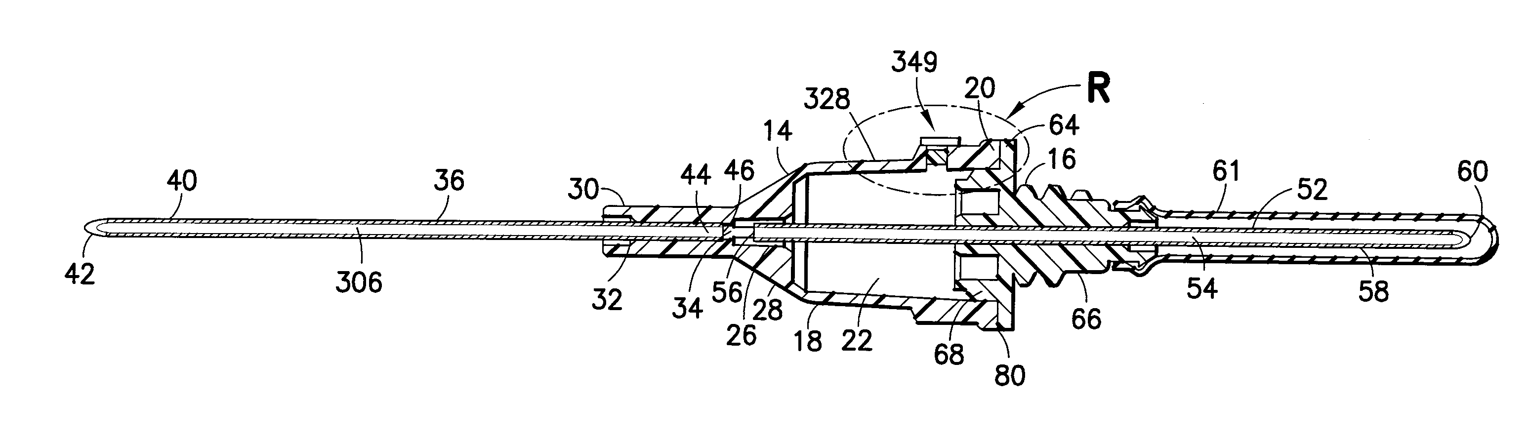
[0051]The present invention provides a self-venting blood collection needle assembly with a self-venting mechanism that permits escape of air, while preventing an outflow of fluid such as blood, that provides a visual indication of vein entry (“flashback”) upon collection of a blood or other fluid sample from a patient into one or more evacuated blood collection tubes.

[0052]It should be noted that the vent media could be, for example, a distinct physical element such as a plug or insert, a integral portion of a device that has been treated such as by laser drilling or has been formed in whole or in part from a porous material, or a coating, layer, etc. formed by disposing a material onto the device, e.g., by dipping, coating, spraying or the like.

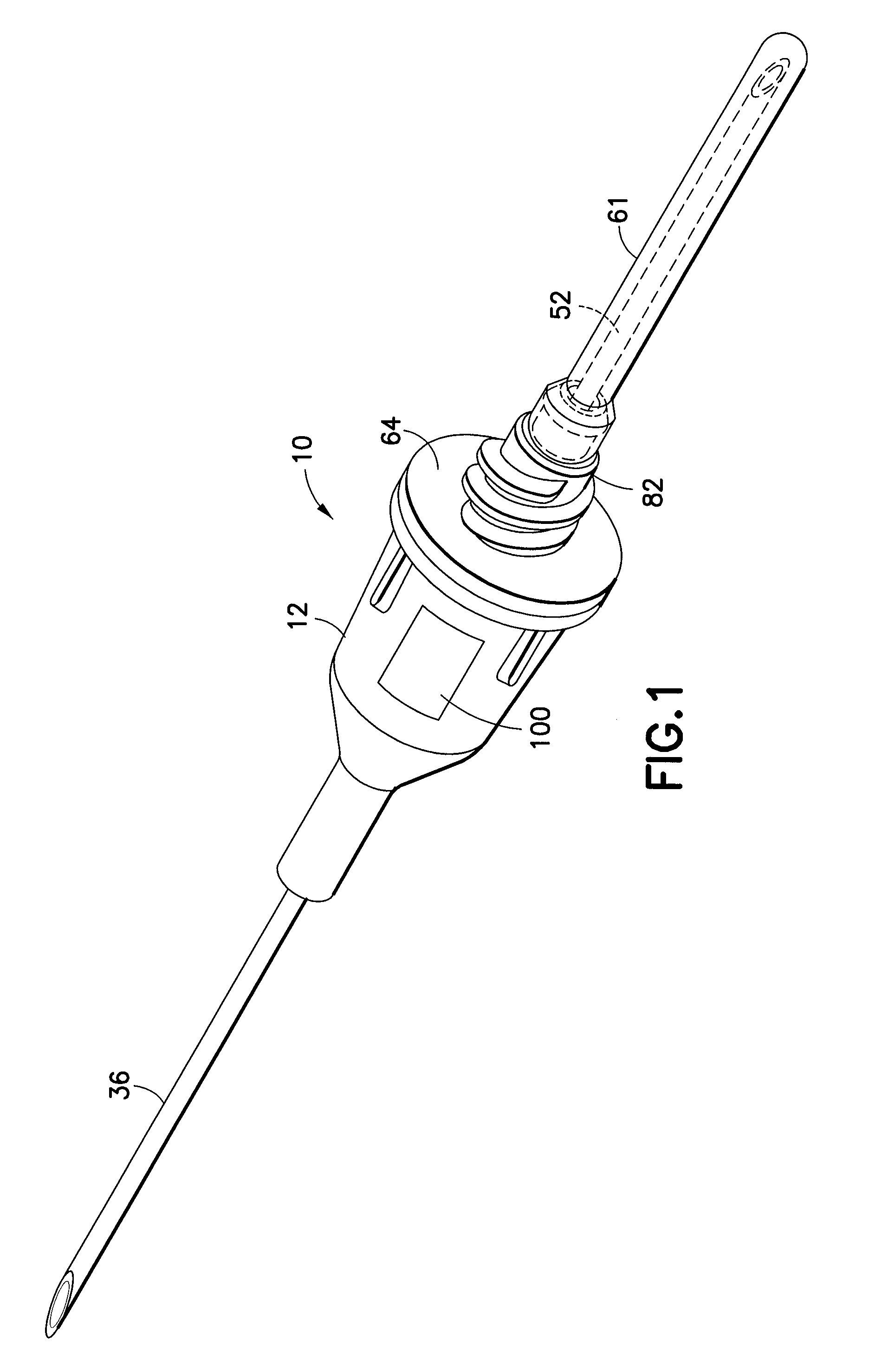
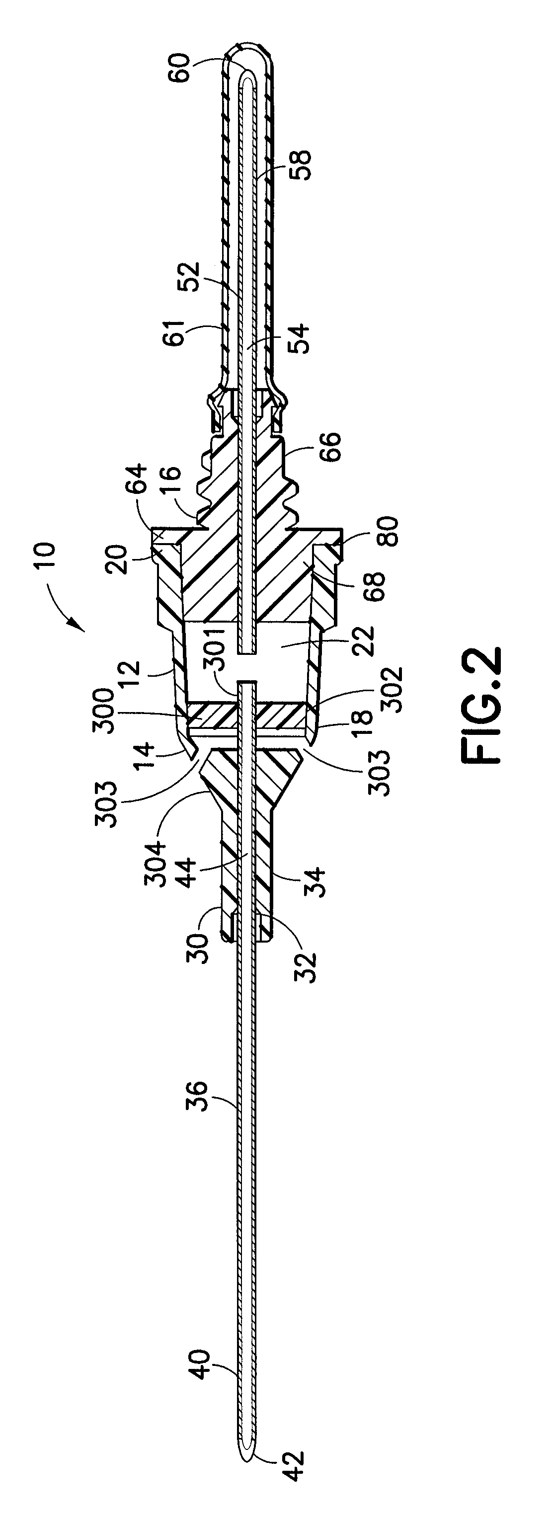
[0053]A blood collection needle assembly in accordance with an embodiment of the subject invention is identified in FIG. 1. A needle assembly 10 includes a hub 12, which supports a fluid inlet needle (first cannula) 36 on one side and a flu...


PUM


Abstract

The invention is a self-venting blood collection needle assembly for the extraction of at least one fluid sample into an evacuated container for laboratory testing, this blood collection needle assembly providing a clear or translucent flashback chamber for blood to flow into, for visualization by the user to confirm successful vein entry. The self-venting mechanism permits escape of air during use, and which, typically, also prevents an outflow of fluid, such as blood. Thus, air under venous pressure will be allowed to escape from the blood collection needle assembly until blood reaches the venting mechanism.

Description

[0001]The present application is a continuation of U.S. patent application Ser. No. 11 / 962,173, filed Dec. 21, 2007, which is a continuation of U.S. patent application Ser. No. 11 / 141,588, filed May 31, 2005, which claims priority to U.S. Provisional Patent Application Ser. No. 60 / 576,217, which was filed on Jun. 2, 2004.BACKGROUND OF THE INVENTION[0002]1. Field of the Invention[0003]The present invention relates to a device for collecting blood samples by performing venipuncture on a patient. More particularly, the present invention relates to a needle assembly for multiple sample blood collection that allows a phlebotomist to determine whether vein entry has occurred, via a self-venting feature, when collecting a blood sample from a patient into an evacuated blood collection tube.[0004]2. Description of Related Art[0005]Venipuncture is the primary method used for acquiring blood samples for laboratory testing. In performing venipuncture procedures, a phlebotomist must follow sever...

Claims


Application Information

Patent Timeline
Patent Type & Authority Applications(United States)
IPC IPC(8): A61B5/15A61B5/00A61M5/158A61M5/32
CPCA61B5/1422A61B5/15003A61B5/150213A61B5/150389A61B5/150488A61B5/150496A61B5/150572A61B5/150732A61B5/1545
Inventor CONWAY, HUGH T.NAIR, HAREESHSWENSON, KIRKNEWBY, C. MARKBLOCH, CURTISLEVY, RICHARDWILKINSON, BRADLEYSCHNEIDER, JAMESTOWNS, BRYANISKRA, MICHAELMARSDEN, STEWART
Owner BECTON DICKINSON & CO
Why Eureka
Try Eureka