Instruments and methods for implanting corneal implant via extra-and intra-cameral routes

a corneal implant and intra-cameral route technology, applied in the field of devices and methods for using ocular and non-ocular implants, can solve the problems of high intraocular pressure of glaucoma, high risk of failure, and high labor intensity of surgeons, and achieve the effect of enhancing shunt engagemen

Inactive Publication Date: 2009-02-12
BECTON DICKINSON & CO
View PDF34 Cites 30 Cited by
  • Summary
  • Abstract
  • Description
  • Claims
  • Application Information

AI Technical Summary

Benefits of technology

[0011]The foregoing and / or other aspects of the present invention are achieved by providing an apparatus including: a transcorneal shunt with a head and a foot, each having a hole therein; and an insertion tool to insert the transcorneal shunt into a corneal incision. The insertion tool includes a stabilizer, and an engager protruding from the stabilizer and releasably engaging the shunt. When the stabilizer contacts one of the head and foot and surrounds the corresponding hole, the engager is inserted, at least partially, into the corresponding hole, and at least a portion of an inserted length of the engager includes an irregularity to enhance shunt engagement.

Problems solved by technology

A major symptom of glaucoma is a high intraocular pressure, or “IOP,” which is caused by the trabecular meshwork failing to drain enough aqueous humor fluid from within the eye.
These procedures are very labor intensive for the surgeons and may be subject to failure due to scarring and cyst formations.
Another problem often related to the treatment of glaucoma with drugs relates to the challenge of delivering drugs to the eye.
Current methods of delivering drugs to the eye are not as efficient or effective as desirable.
Drops are an inefficient way of delivering drugs; much of the drug never reaches the inside of the eye.
Drugs may be injected into the eye, but this is often traumatic and the eye typically needs to be injected on a regular basis.

Method used


Image

  • Instruments and methods for implanting corneal implant via extra-and intra-cameral routes
  • Instruments and methods for implanting corneal implant via extra-and intra-cameral routes
  • Instruments and methods for implanting corneal implant via extra-and intra-cameral routes

Examples


Embodiment Construction

[0041]Reference will now be made in detail to embodiments of the present invention, examples of which are illustrated in the accompanying drawings, wherein like reference numerals refer to the like elements throughout. The embodiments described explain the present invention by referring to the figures.

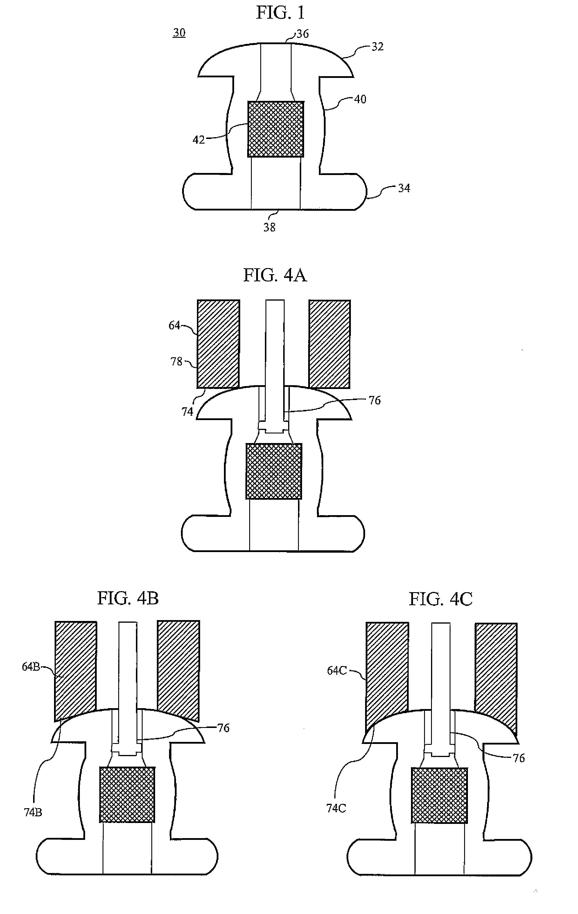
[0042]FIG. 1 illustrates a cross section of an ophthalmic shunt 30 according to an embodiment of the present invention, for example, a transcorneal shunt 30. The shunt 30 has a head 32 and a foot 34, each having the hole 36, 38 therein. A body 40 that forms a conduit extends between the head 32 and foot 34. According to one embodiment, the conduit 20 includes a filter 42 designed to restrict bacteria from infiltrating into the eye through the shunt and control a flow rate of aqueous humor from the anterior chamber of the eye to the outside surface of the cornea.

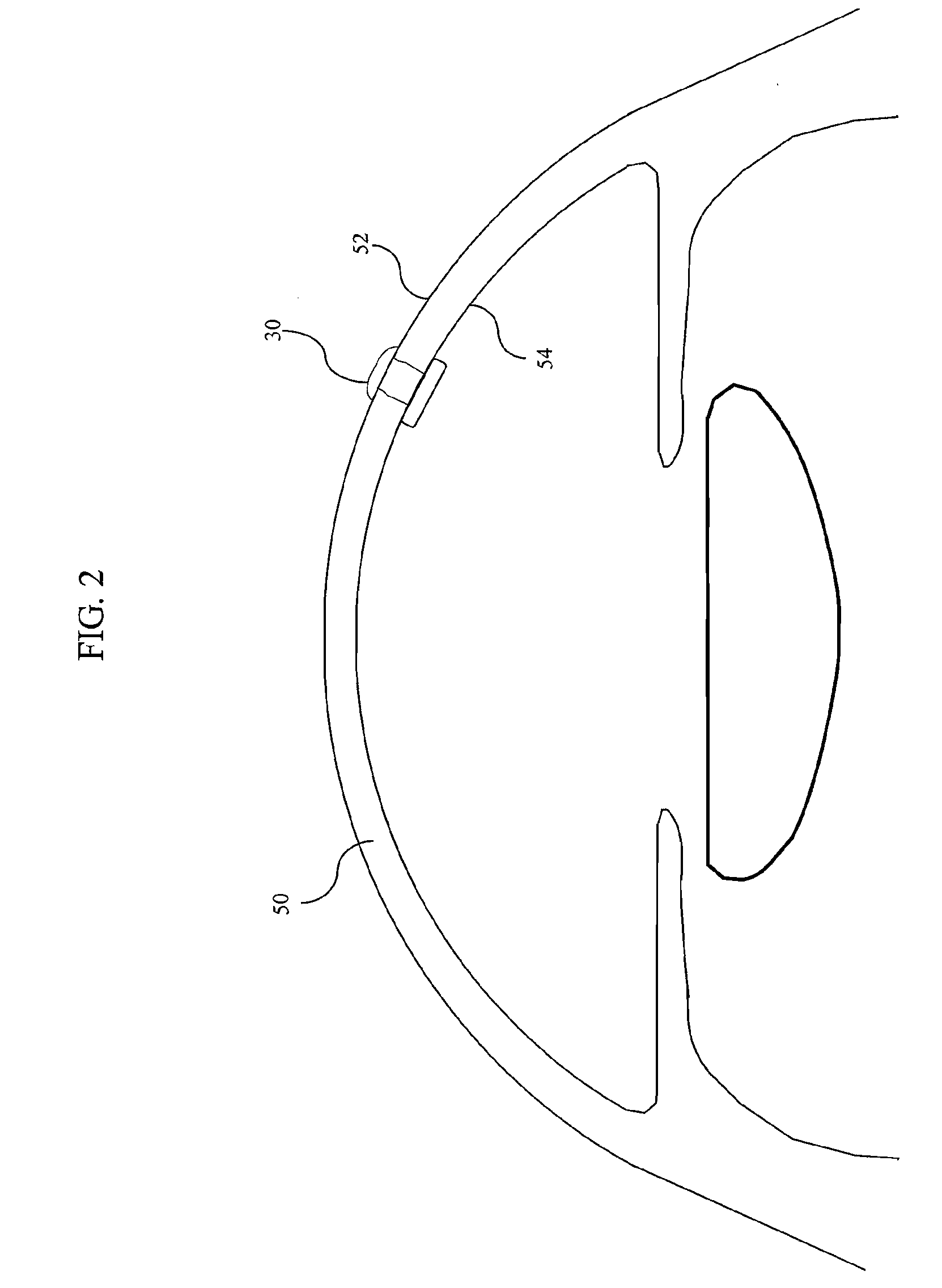
[0043]FIG. 2 illustrates a cross section of the ophthalmic shunt of FIG. 1 implanted in a cornea 50. As shown in FIG. 2, the t...


PUM


Abstract

A method of implanting a transcorneal shunt into a cornea, the shunt having a head and a foot, each having a hole therein, the method including the operations of engaging an insertion tool with a foot hole of the shunt; making an entry incision in the cornea; inserting the shunt, while still engaged with the insertion tool, through the entry incision; making an implant incision in the cornea; inserting the head of the shunt through the implant incision to position and seat the shunt; and releasing the shunt from the insertion tool.

Description

BACKGROUND OF THE INVENTION[0001]1. Field of the Invention[0002]The present invention relates to devices and methods for use with ocular and non-ocular implants. More particularly, certain implementations of the present invention relate to insertion tools and methods for the controlled insertion of an ophthalmic shunt into an eye to relieve intraocular pressure via extra- and intra-corneal routes.[0003]2. Description of the Related Art[0004]Glaucoma, a condition caused by optic nerve cell degeneration, is the second leading cause of preventable blindness in the world today. In the human eye, aqueous humor is a transparent liquid that is constantly secreted by the ciliary body around the lens and flows into the region of the eye between the cornea and the lens, the anterior chamber. The trabecular meshwork provides the means by which the aqueous humor naturally drains from the anterior chamber. A major symptom of glaucoma is a high intraocular pressure, or “IOP,” which is caused by t...

Claims


Application Information

Patent Timeline
Patent Type & Authority Applications(United States)
IPC IPC(8): A61M27/00
CPCA61F9/00781
Inventor BENE, ERIC A.MCGRAW, MICHAEL J.TAYLOR, MARGARETBOWEN, MARKLEE, ED
Owner BECTON DICKINSON & CO
Why Eureka
Try Eureka