
Fluid jet device

a technology of fluid jets and jets, which is applied in the field of fluid jet devices, can solve the problems of heat of the fluid jets coming from there, adversely affecting any normal tissue or others, and the actual-possible frequency of driving is about 100 hz, so as to improve the pressure in the fluid chamber, improve the effect of fluid flow, and operate stably

Active Publication Date: 2009-02-12
SEIKO EPSON CORP
View PDF12 Cites 18 Cited by
  • Summary
  • Abstract
  • Description
  • Claims
  • Application Information

AI Technical Summary

Benefits of technology

[0011]In the first aspect, because the inlet fluid path is smaller in capacity than the fluid chamber, even if a minute capacity change is observed in the fluid chamber, any effect possibly caused as a result of volume change of a gas in the fluid or the fluid itself can be minimized, thereby being able to instantaneously increase the pressure in the fluid chamber. Utilizing the increase of the pressure and the inertance difference between the inlet and outlet fluid paths, jets of fluid can be produced with efficiently-strong pulsation.
[0012]There is another effect that, by including such a pump or others for discharging a fluid at any predetermined pressure, the device can be operated stably.
[0014]With such a configuration, the length of the outlet fluid path, i.e., the distance between the fluid jet aperture section and the fluid chamber, is reduced, and this thus allows transmission of pulsation generated in the fluid chamber to the fluid jet aperture section with no attenuation, thereby being able to produce jets of fluid with efficiently-strong pulsation.
[0020]Such a configuration allows to simplify the configuration of the fluid jet device with no additional component such as pipe.
[0024]With such a configuration, with a groove of a semicircular cross section formed on the joint surface of the two side-wall configuring members, for example, the fluid path can be circular in shape. This favorably leads to the effect of being able to derive optimum values for the fluid path, e.g., the cross-sectional area thereof, the length thereof, and the cross-sectional shape thereof with ease.
[0026]Including a cover member as such can protect the pulsation generation section, and can also reduce any possibility of damaging a body part to be operated during surgery or others even if the tip end of the fluid jet device touches the body part.

Problems solved by technology

The problem with the fluid jet device of Patent Document 1 is that, however, jets of fluid coming therefrom are heated because of the configuration of producing jets of fluid by steam bubbles of the fluid.
The heat may thus adversely affect any normal tissue or others.
There is another problem that the actually-possible frequency for driving is about 100 Hz at the maximum because producing a jet of fluid is not allowed until the steam bubbles are disappeared.
The fluid jet device of Patent Document 1 has still another problem that the device cannot be available for use to remove any thrombus in blood vessels by jets of fluid directed from a fluid jet aperture section provided at the tip of a catheter, for example.

Method used


Image

  • Fluid jet device
  • Fluid jet device
  • Fluid jet device

Examples


first embodiment

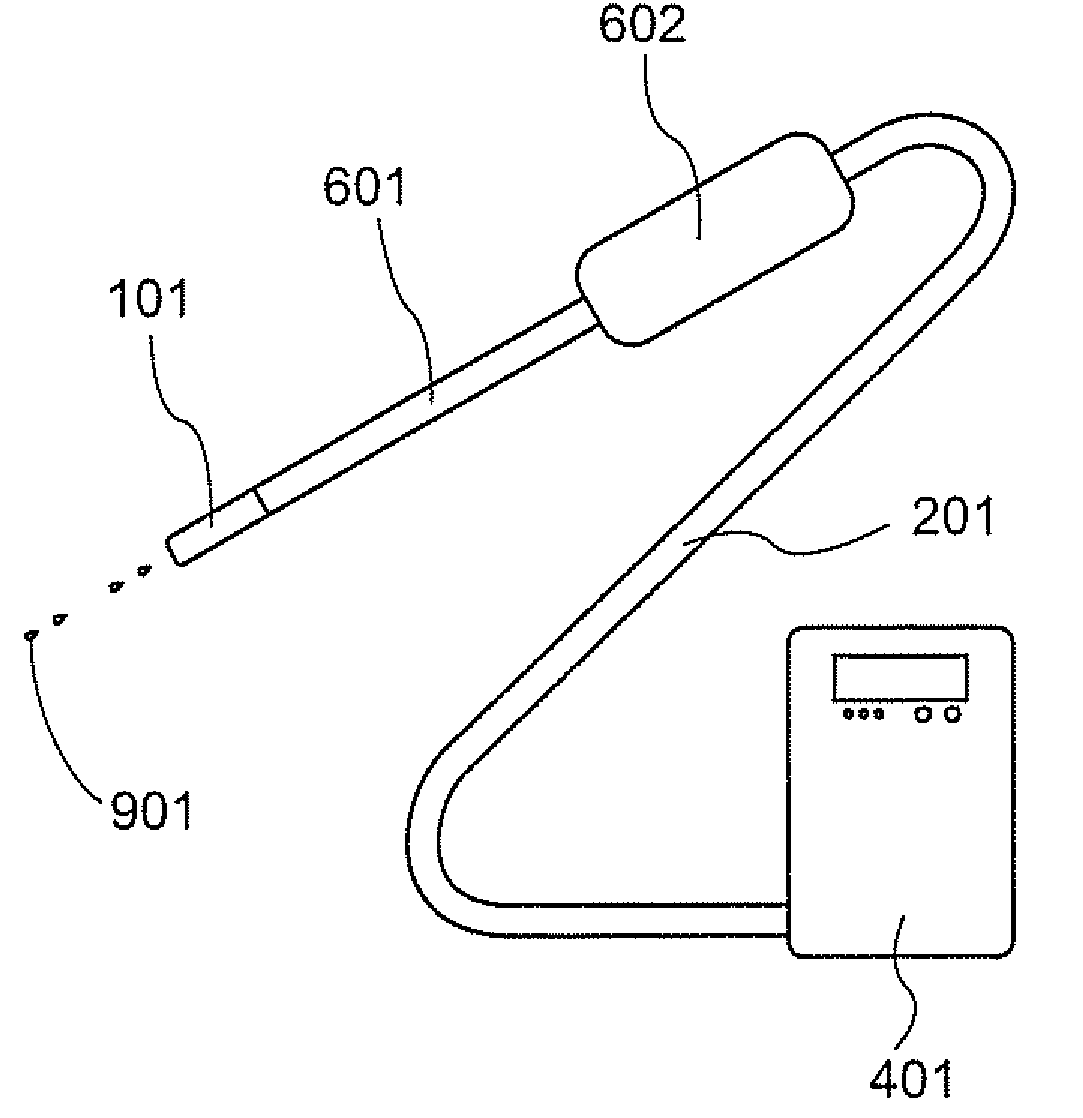
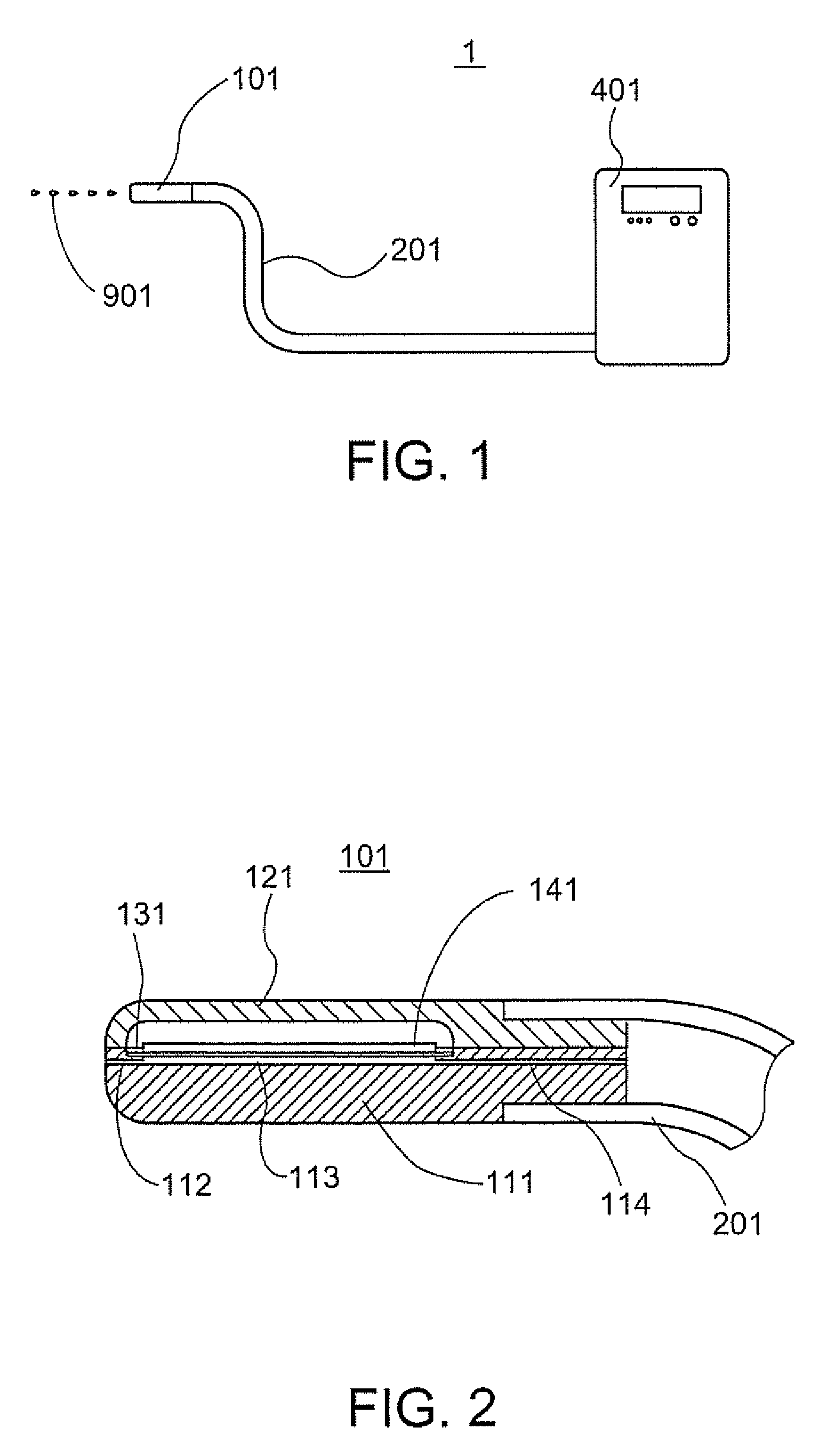
[0045]FIG. 1 is a diagram showing the schematic configuration of a fluid jet device of a first embodiment. In FIG. 1, a fluid jet device 1 is configured to include, basically, a pressure generation section 401, a pulsation generation section 101, and a connection tube 201. The pressure generation section 401 carries therein a fluid, and discharges the fluid at any predetermined pressure with the workings of a pump or others. The pulsation generation section 101 changes the fluid provided at the predetermined pressure as such into pulsation. The connection tube 201 is flexible, and serves to establish a connection between the pressure generation section 401 and the pulsation generation section 101. Herein, the wiring needed for driving the pulsation generation section 101 is disposed along the connection tube 201 (not shown).

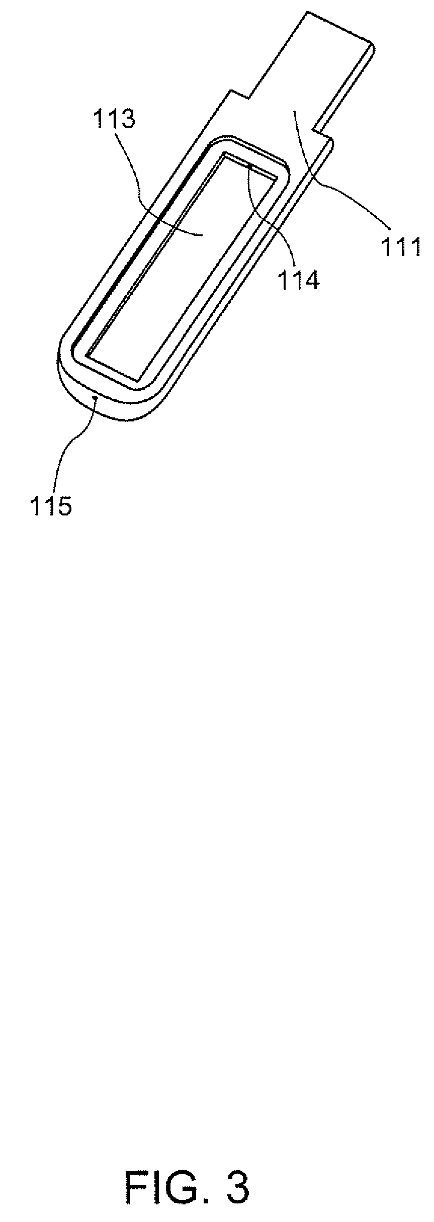
[0046]Described next is the pulsation generation section 101 of the first embodiment by referring to FIGS. 2 to 4. FIG. 2 is a vertical cross-sectional view of t...

second embodiment

[0076]Described next is a fluid jet device of a second embodiment by referring to the accompanying drawings.

[0077]In the second embodiment, diaphragms each affixed with a piezoelectric element are disposed to oppose each other with a fluid chamber sandwiched therebetween, and the diaphragms serve to seal the fluid chamber. With such a configuration, the fluid chamber can remain small in size but the capacity change thereof can be large, thereby being able to produce jets of fluid with more intensity. Herein, any component similar to that in the first embodiment is provided with the same reference numeral and described, and any operation similar thereto is not described twice.

[0078]FIG. 5 is a partial cross-sectional view of a pulsation generation section of the second embodiment, and FIG. 6 is a perspective view of main components of the pulsation generation section.

[0079]In FIGS. 5 and 6, a pulsation generation section 301 is provided with a fluid path forming plate 311, which is m...

third embodiment

[0087]Described next is a third embodiment by referring to the accompanying drawings. In the third embodiment, characteristically, at least either the inlet or outlet fluid path is configured by a groove portion formed to a fluid path forming plate and a diaphragm.

[0088]FIG. 7 is a vertical cross-sectional view of main components in a pulsation generation section of the third embodiment. The configuration of the third embodiment other than the inlet and outlet fluid paths is the same as that in the second embodiment described above, and thus is not described again. In the third embodiment, any component similar to that in the second embodiment is provided with the same reference numeral and described.

[0089]Similarly to the second embodiment, a fluid path forming plate 511 is formed with a through hole in the thickness direction, thereby forming the fluid chamber 313. On one surface of the fluid path forming plate 511, a U-shaped groove portion is provided for forming an outlet fluid...


PUM


Abstract

A fluid jet device being provided with a fluid jet aperture section and producing a jet of fluid from the fluid jet aperture section includes: a pulsation generation section including a fluid chamber whose capacity can be changed, an inlet fluid path linked through the fluid chamber with a volume smaller than that of the fluid chamber, and an outlet fluid path linked through the fluid chamber and the fluid jet aperture section with an inertance set smaller than that of the inlet fluid path; and a pressure generation section that supplies the fluid to the inlet fluid path.

Description

BACKGROUND[0001]1. Technical Field[0002]The present invention relates to a fluid jet device that is compact and lightweight yet produces a jet of fluid by strong high-frequency pulsation.[0003]2. Related Art[0004]A previous fluid jet device for use to cut open or cut and remove living body tissue is known with a fluid jet generation method of producing jets of pulsating fluid at high speed. For producing jets of fluid at high-speed as such, the fluid jet device is provided with means for flowing a fluid into a fluid chamber, and intermittently generates steam bubbles from the fluid using heating means in the fluid chamber so that the internal pressure is intermittently increased in the fluid chamber. An example includes Patent Document 1 (JP-T-2003-500098).[0005]According to Patent Document 1, a fluid has been instantaneously heated by discharge of a high-voltage electrode or others, and utilizing the pressure generated by such heating, higher-speed jets of fluid have been produced....

Claims


Application Information

Patent Timeline
Patent Type & Authority Applications(United States)
IPC IPC(8): A61B17/3203A61B17/22
CPCA61B17/3203A61B2017/00402A61B17/32037
Inventor SETO, TAKESHITAKAYAMA, KAZUYOSHI
Owner SEIKO EPSON CORP
Learn More