Spring loaded spacer

Inactive Publication Date: 2009-02-19
RICHCO
View PDF11 Cites 15 Cited by
  • Summary
  • Abstract
  • Description
  • Claims
  • Application Information

AI Technical Summary

Benefits of technology

[0008]It is the object of the present invention to provide a spring loaded spacer of the character described.
[0009]Another object is to provide a spring loaded spacer for a touch control panel which is fully assembled and ready for installation.
[0010]Another object is to provide a spring loaded spacer which can accommodate one or more printed circuit boards or other components.
[0011]Another object is to provide a spring loaded spacer which can provide continuous

Problems solved by technology

These assemblies take a significant amount of time and effort to put together.
The parts and printed circuit board are critical and assembly error can result in damage to the equipment or lessen the life of the appliance in whi

Method used


Image

  • Spring loaded spacer
  • Spring loaded spacer
  • Spring loaded spacer

Examples


Embodiment Construction

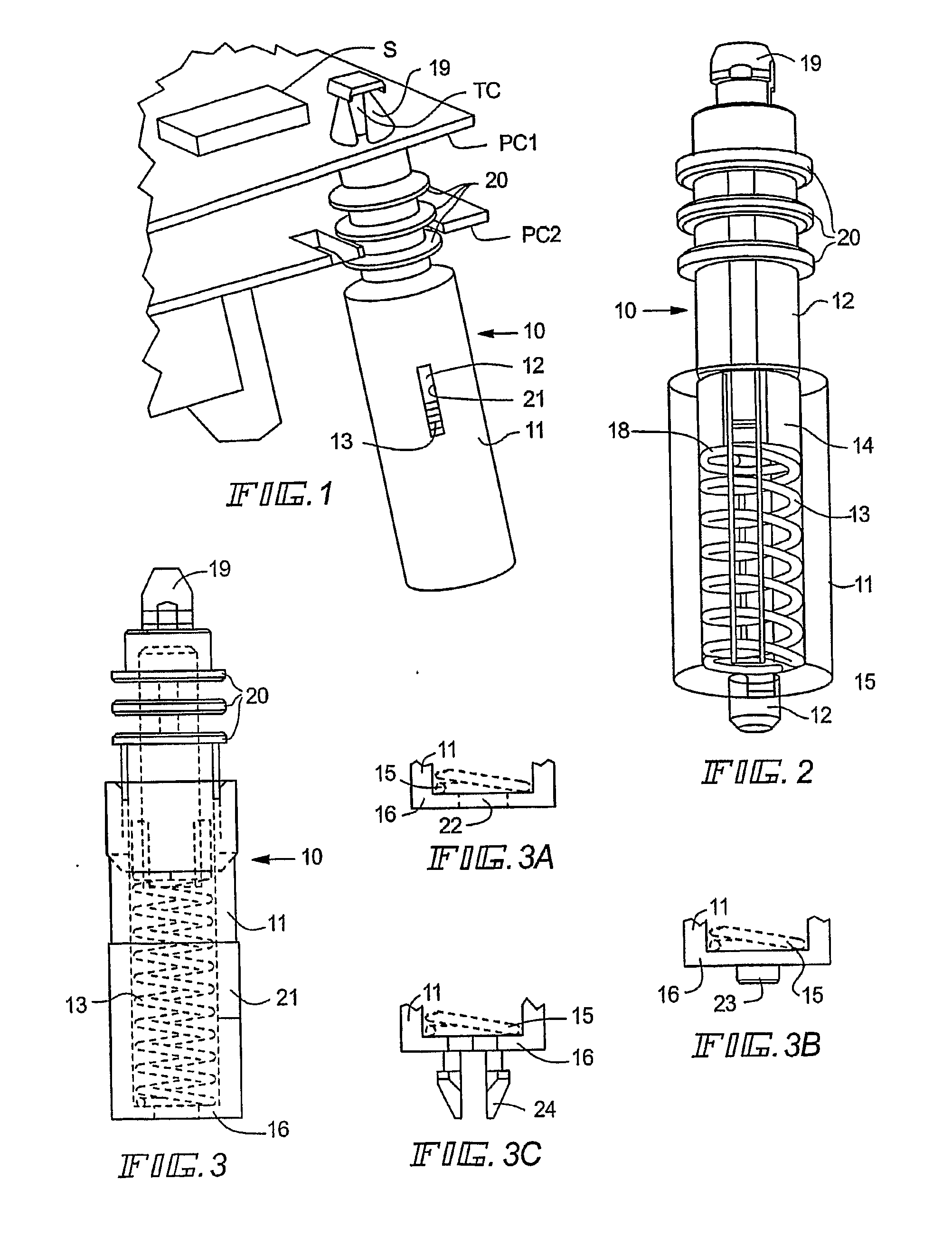
[0026]With reference to FIG. 1, a spring loaded spacer 10 is connected to upper printed circuit board PC1 and lower printed circuit board PC2. Components such as a touch control TC and a light sensor S may be secured on the printed circuit board PC1, as shown. Such a spacer 10 is normally installed on a chassis or underlying panel (not shown), and when installed the spacer is biased away from the chassis and toward the printed circuit boards PC1 and PC2.

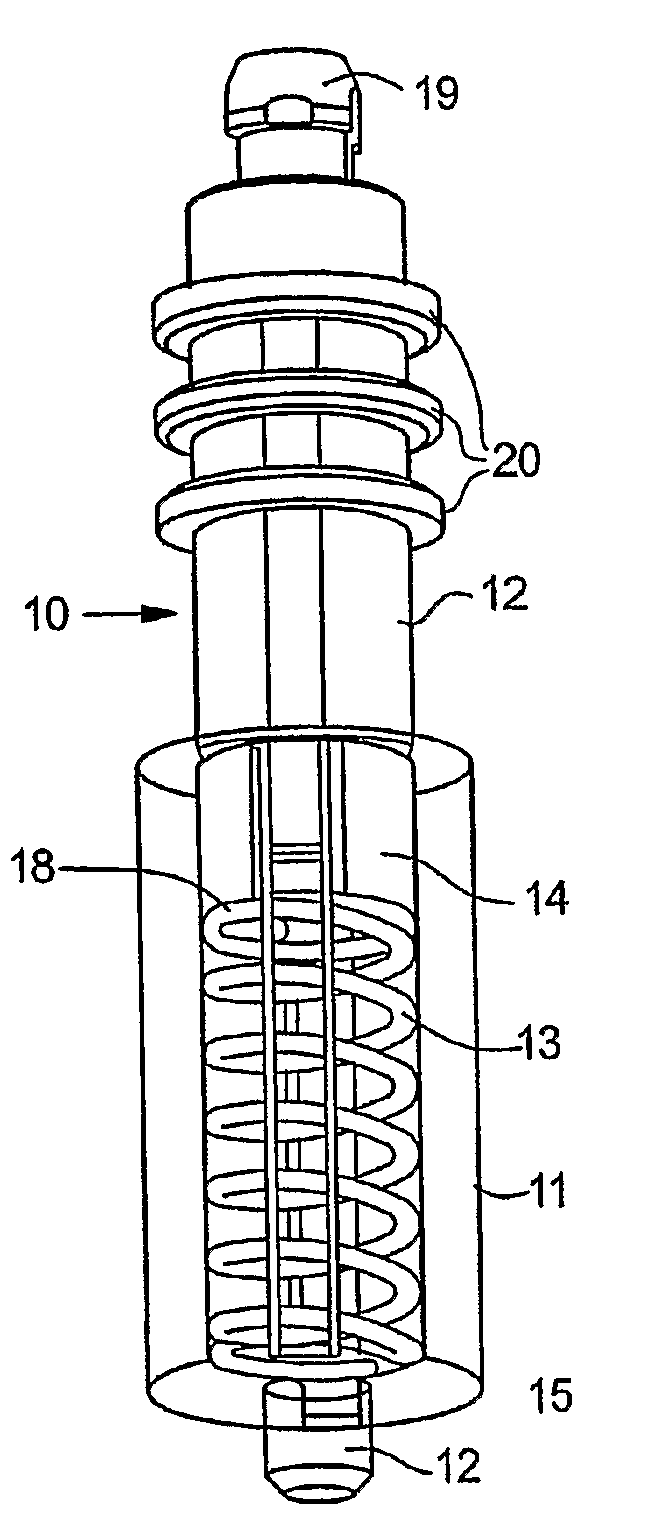
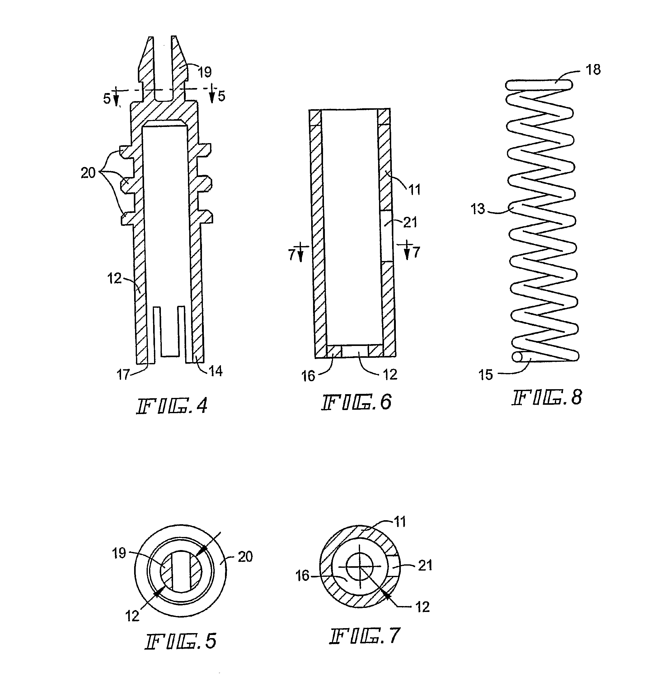
[0027]As shown in FIG. 2, this spring loaded spacer 10 consists of a barrel member 11 having mounting means 12 for connecting the barrel member to an underlying chassis or panel (not shown). The barrel member receives a shank 12 and compression spring 13. The compression spring 12 is installed on a shaft 14 formed on the shank 12 and the spring 13 has a formed end 15 adapted to seat on the bottom 16 of the barrel member 11. Legs 17 are formed in the shank spaced away from the bottom of the shaft 14 to capture the upper end 18 of the ...


PUM


Abstract

A spring loaded spacer for fastening components and control units with touch control face plates or panels wherein the spacer has a barrel portion having at one end means for connecting the spacer to a chassis or the like and at its other end a shank for connecting it to one or more printed circuit boards and/or components or the like, wherein a spring loaded shank is seated within the barrel and is adapted to receive one or more printed circuit boards under tensioned engagement.

Description

[0001]This invention relates to spring loaded spacers, and is more particularly directed to such products, preferably fabricated from plastic and having insulating qualities, and capable of use in fastening systems for components and control units with touch control face plates or panels.BACKGROUND AND SUMMARY OF THE INVENTION[0002]Typically, in conventional touch control assemblies, for example, in oven top touch control panels, a separate spring, a separate spacer and often other parts are connected together with a printed circuit board. These assemblies take a significant amount of time and effort to put together. Parts must be properly sized and substantial facility is required for the assembly. The parts and printed circuit board are critical and assembly error can result in damage to the equipment or lessen the life of the appliance in which they are used. Further such parts are not usually interchangeable, and while many fastening systems may be required for a single applianc...

Claims


Application Information

Patent Timeline
IPC IPC(8): B60G11/14
CPCF16F1/128F16F9/54F16F2230/0047Y10T24/44026H05K2201/042H05K2201/2036Y10T24/42H05K1/144B60G11/00B60G11/14F16F9/32
Inventor REISEL, ROBERTCONWAY, IANVOLKER, WILLIM
Owner RICHCO
Why Eureka
Try Eureka