Power conversion system

a power conversion system and power conversion technology, applied in the direction of dynamo-electric converter control, electric generator control, piston pump, etc., can solve the problems of high-speed machine requirements for both high power and high fundamental frequency that are beyond the capability of conventional industrial drive systems, excessive rotor heating, and high torque ripple with low order harmonics

Inactive Publication Date: 2009-02-19
GENERAL ELECTRIC CO
View PDF20 Cites 82 Cited by
  • Summary
  • Abstract
  • Description
  • Claims
  • Application Information

AI Technical Summary

Benefits of technology

[0010]It would be desirable to have an improved converter system...

Problems solved by technology

In some applications, high-speed machine requirements for both high power and high fundamental frequency are beyond the capability of conventional industrial drive systems.
For example, limited switching frequency capabilities of conventional high power devices result in three-level configurations not being used to reach beyond 200 Hz fundamental frequency with acceptable power quality at the machine terminals.
Challenges include excessive rotor heating (in induction machines) or rotor shield heating (in permanent magnet machines) and high torque ripple with low order harmonics.
Five level architectures with neutral-point clamped or flying-capacit...

Method used


Image

  • Power conversion system
  • Power conversion system
  • Power conversion system

Examples


Embodiment Construction

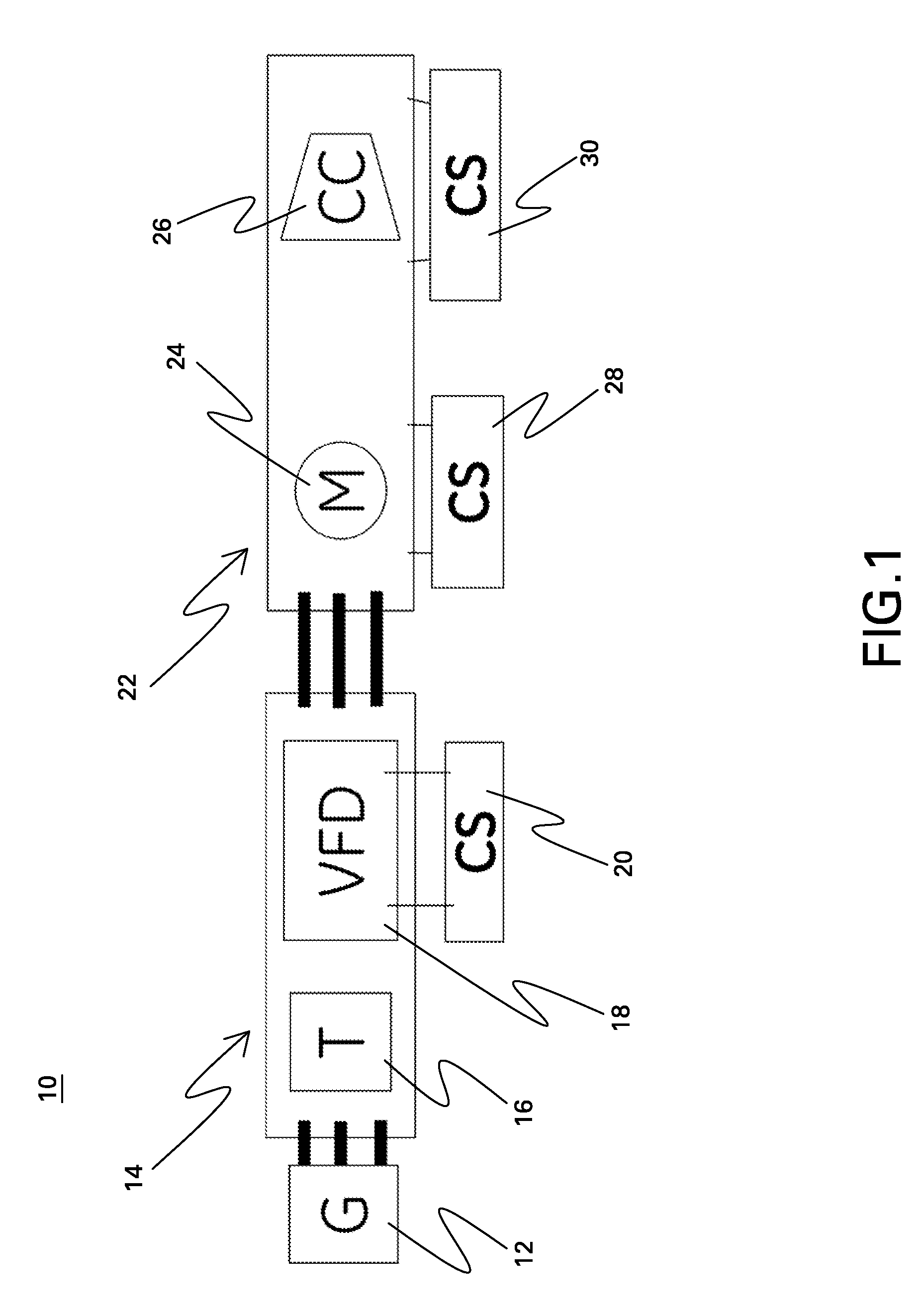
[0024]FIG. 1 is a block diagram of a power conversion system 10. In the embodiment of FIG. 1, power is initially supplied from a power grid 12 to a drive system 14 that converts the power for use in a machine system 22. Power grid 12 is typically a 50 Hz or 60 Hz grid. Drive system 14 is shown for purposes of example in FIG. 1 as including an input transformer 16, a variable frequency drive 18, and a controller 20. Machine system 22 is shown for purposes of example as including a motor 24 driving a compressor 26 and as including associated controllers 28 and 30. Although a plurality of controllers is shown, the controls may be embodied in a single unit or a plurality of units. Embodiments disclosed herein are believed to be particularly useful for driving high-speed electrical machines such as motors used in oil and gas recovery.

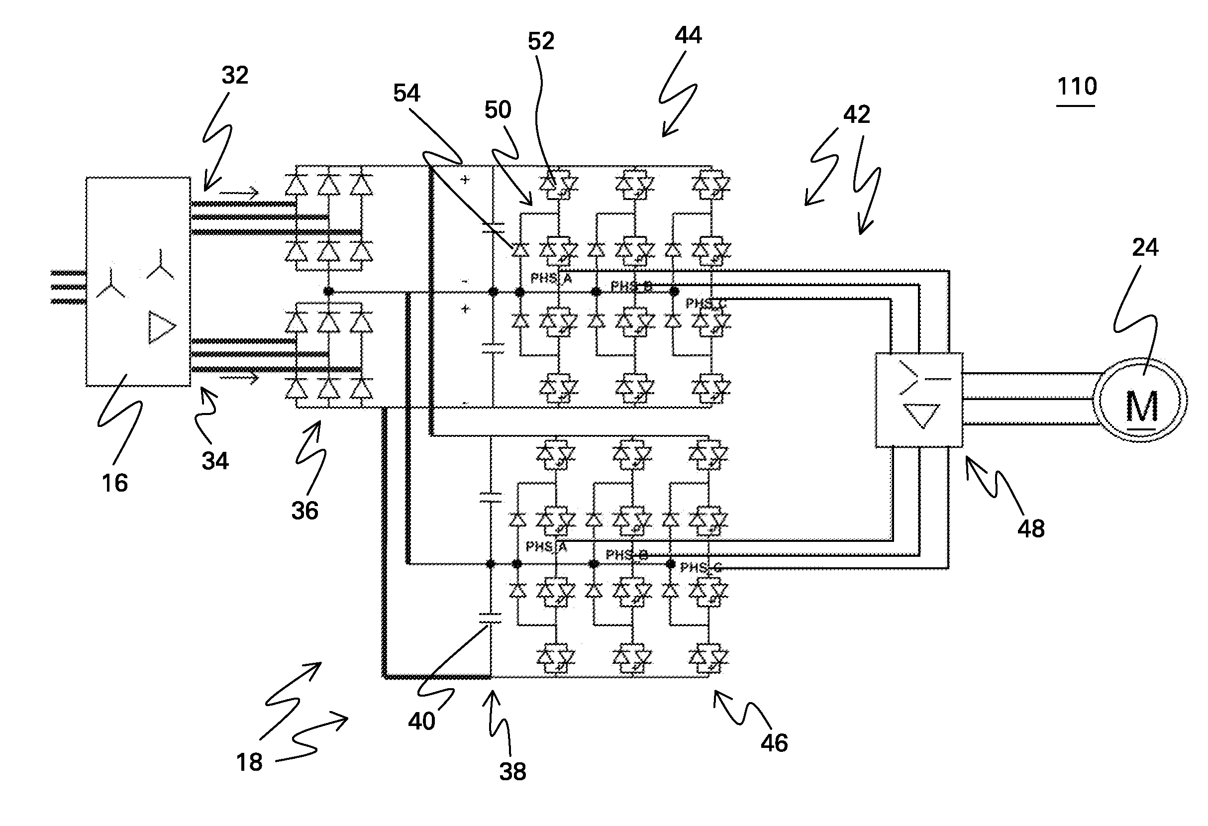
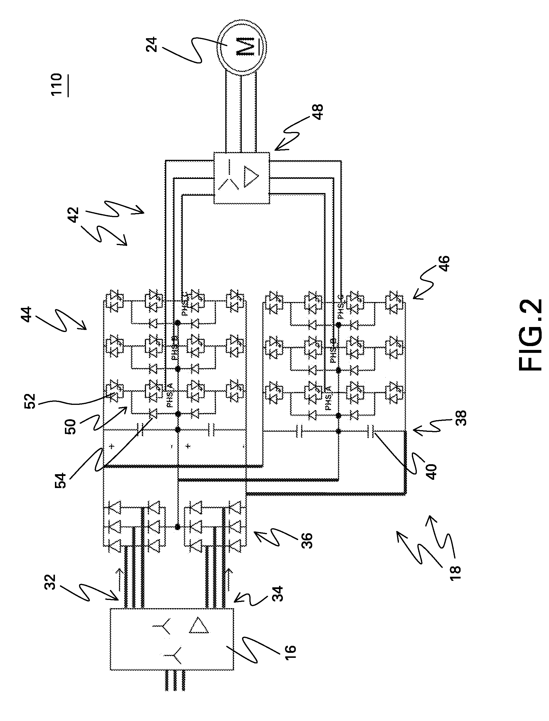
[0025]FIG. 2 is a circuit diagram including a converter topology in accordance with embodiments disclosed herein wherein power conversion system 110 compris...


PUM


Abstract

A power conversion system includes two three-level converters, and a phase shifted transformer coupled to the converters.

Description

BACKGROUND[0001]The systems disclosed herein relate generally to power conversion systems and more specifically to power conversion systems that are particularly suitable for high-speed machines.[0002]High-speed compressor drive trains for oil and gas applications would benefit from high-speed electrical machines operating at multi-megawatt power levels. Such high-speed machines would also be useful for directly driving generators with gas turbines for shipboard and mobile power generation applications.[0003]High-speed machines are machines with either a high mechanical speed of the rotor or a high electrical frequency (which is a function of the mechanical speed and the number of poles of the machine). In one example, high-speed is defined as being at least 6000 rpm and is typically on the order of 25,000 rpm for lower power machines and 7000 rpm for higher power machines. In another example, high frequency is defined as being at least 100 Hz or more specifically on the order of 40...

Claims


Application Information

Patent Timeline
IPC IPC(8): H02P9/00F04B17/00H02M7/00
CPCH02M7/49H02M7/487
Inventor DATTA, RAJIBRITTER, ALLEN MICHAELWENG, HAIQINGGARCES, LUIS JOSECHEN, KUNLUNZHANG, HAITAO
Owner GENERAL ELECTRIC CO
Why Eureka
Try Eureka