Pulse doppler coherent method and system for SNR enhancement

a coherent and pulse-doppler technology, applied in the direction of reradiation, measurement devices, instruments, etc., can solve the problems of blind zones (blind ranges and doppler frequencies) in the detection map, loss and degradation of detection probability, and achieve the effect of maximizing the results of the integration procedur

Active Publication Date: 2009-02-19
ELTA SYST LTD
View PDF21 Cites 13 Cited by
  • Summary
  • Abstract
  • Description
  • Claims
  • Application Information

AI Technical Summary

Benefits of technology

[0013]An object of the present invention is to maximize the results of integ

Problems solved by technology

However this scheme does not support unambiguous measurement of range or velocity or both.
Another problem related to a single PRF scheme of detection is the problem of blind zones (blind ranges and Doppler frequencies) in the detection map.
This problem reflects the periodic nature of transmitting and receiving in pulse radar detect

Method used


Image

  • Pulse doppler coherent method and system for SNR enhancement
  • Pulse doppler coherent method and system for SNR enhancement
  • Pulse doppler coherent method and system for SNR enhancement

Examples


Embodiment Construction

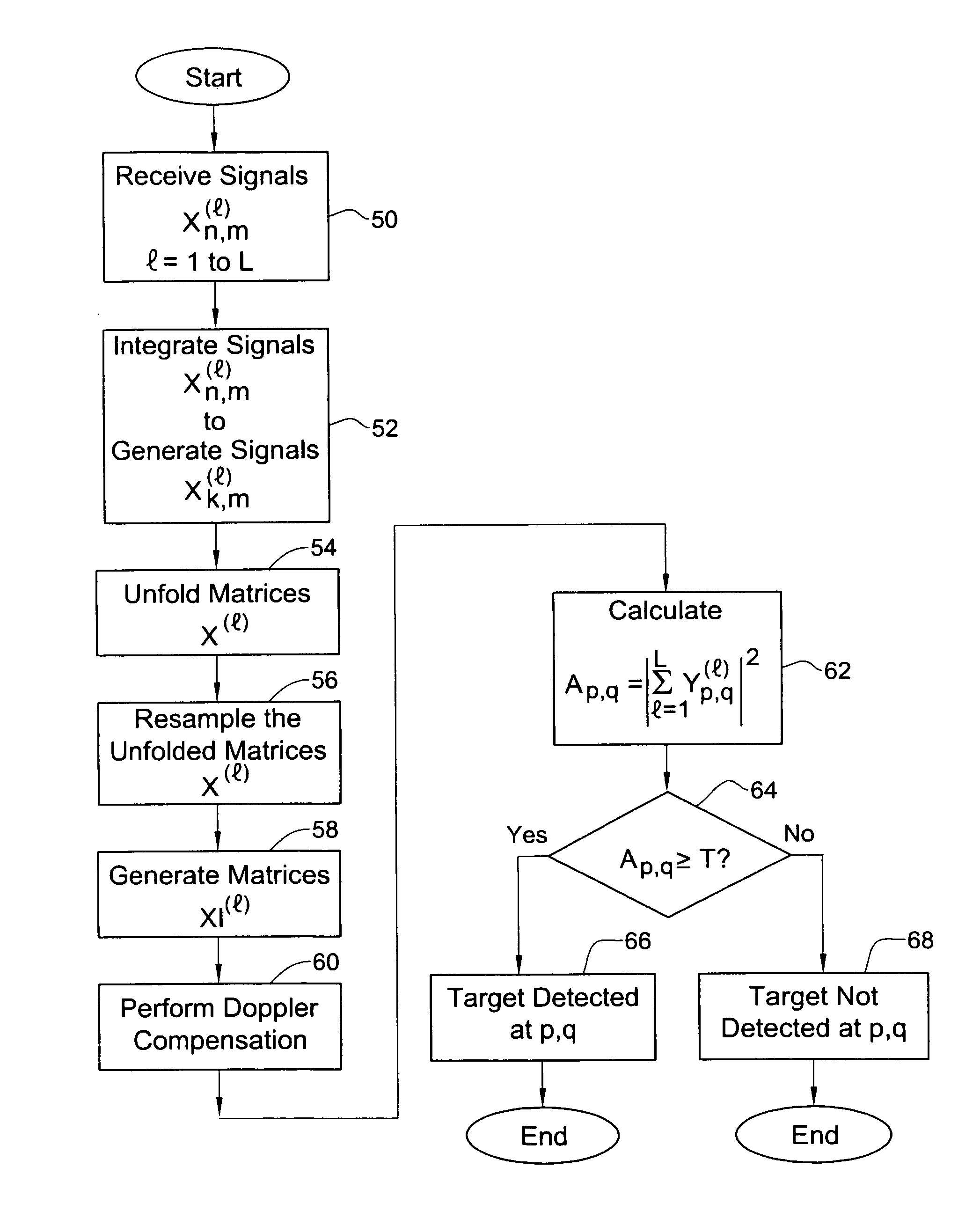
[0023]FIG. 3 shows a method for target detection in a pulse-Doppler coherent system, in accordance with one embodiment of the invention. At 50, a signal xnm(l)=x(l)(tnm) is received for each PRF used, where l=1 to L is the PRF index, L is the number of PRFs used, n is the pulse number in the signal, m is the range gate, and tnm is the sampling time of the signal of the range gate m of the pulse n, given by tn,m(l)=nPRI(l)+mRG+tl, where PRI is the pulse rate interval, RG is the duration of a single range gate and ti is the start time of the l-th CPI counted from some reference point—for example the beginning of the 1-st CPI. At 52, the signals xnm(l) are subjected to coherent integration in which a discrete Fourier transform is performed on the signals xnm(l) to generate a signal

Xkm()=∑n=0N(l)-1xnm(l)wn-2πjknK,k=0,…,K-1,l=0,…,L-1,m=0,…,M(l)-1,

where k is an index of the Doppler frequency, K is the number of Doppler frequencies, N is the number of pulses in the signal, wn is a weightin...


PUM


Abstract

A method and system for SNR enhancement in pulse-Doppler coherent target detection. In accordance with the method of the invention, complex signals are obtained for each of two or more sub-intervals of the time-on-target interval, allowing simultaneous rang and Doppler measurements. A coherent integration is then performed on the signals to generate complex-valued folded matrices. The folded matrices are unfolded and target detection is then performed in a process involving one or more of the unfolded matrices. A pulse-Doppler coherent system is also provided configured for target detection by the method of the invention.

Description

FIELD OF THE INVENTION[0001]The present invention relates to methods and systems for SNR enhancement in a pulse Doppler coherent system.BACKGROUND OF THE INVENTION[0002]The pulse Doppler technique is common to most modern surveillance and tracking radars, and ultrasound systems. This technique employs a sequence of transmitted pulses which impinge on a target, are reflected from the target and are collected back in the receiver. This technique is particularly convenient when the velocity of the target is significantly different from the velocity of the background scatterers such as the ground, trees, foliage and so on. Under this condition, the detection capability of the system is maximized in terms of the signal to noise ratio (SNR) so that the probability of detection is improved.[0003]Most modern surveillance radars scan the surrounding space using a relatively narrow radiation beam. The total scan time is usually the user specified parameter of the system. The fraction of scan ...

Claims


Application Information

Patent Timeline
IPC IPC(8): G01S13/52
CPCG01S13/5246G01S13/227G01S13/53
Inventor BEILIN, ELLAGRIZIM, JEHEZKELVAGMAN, YACOVLOMES, ALEXANDER
Owner ELTA SYST LTD
Why Eureka
Try Eureka