
Liquid crystal display device and electronic device using the same

a technology of liquid crystal display and electronic device, which is applied in the direction of thin material processing, instruments, chemistry apparatus and processes, etc., can solve the problems of reducing the voltage retention rate, affecting the quality etc., to achieve high-quality display, improve the reliability of liquid crystal display devices incorporating photo-alignment films, and prolong the service life

Active Publication Date: 2009-02-19
SHARP KK
View PDF18 Cites 20 Cited by
  • Summary
  • Abstract
  • Description
  • Claims
  • Application Information

AI Technical Summary

Benefits of technology

[0009]The present invention has been made in view of the above problems, and an objective thereof is to improve the reliability of a liquid crystal display device incorporating a photo-alignment film.
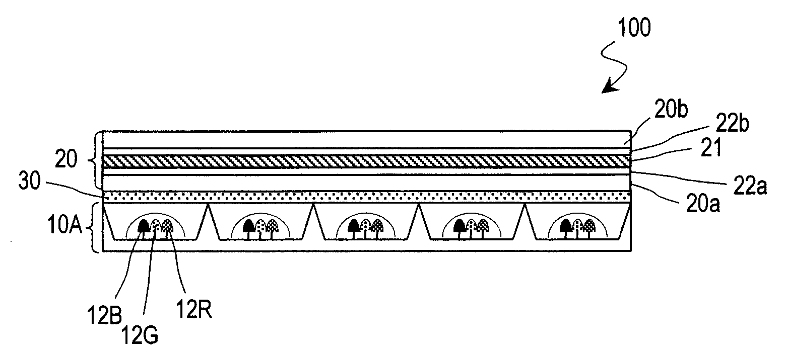
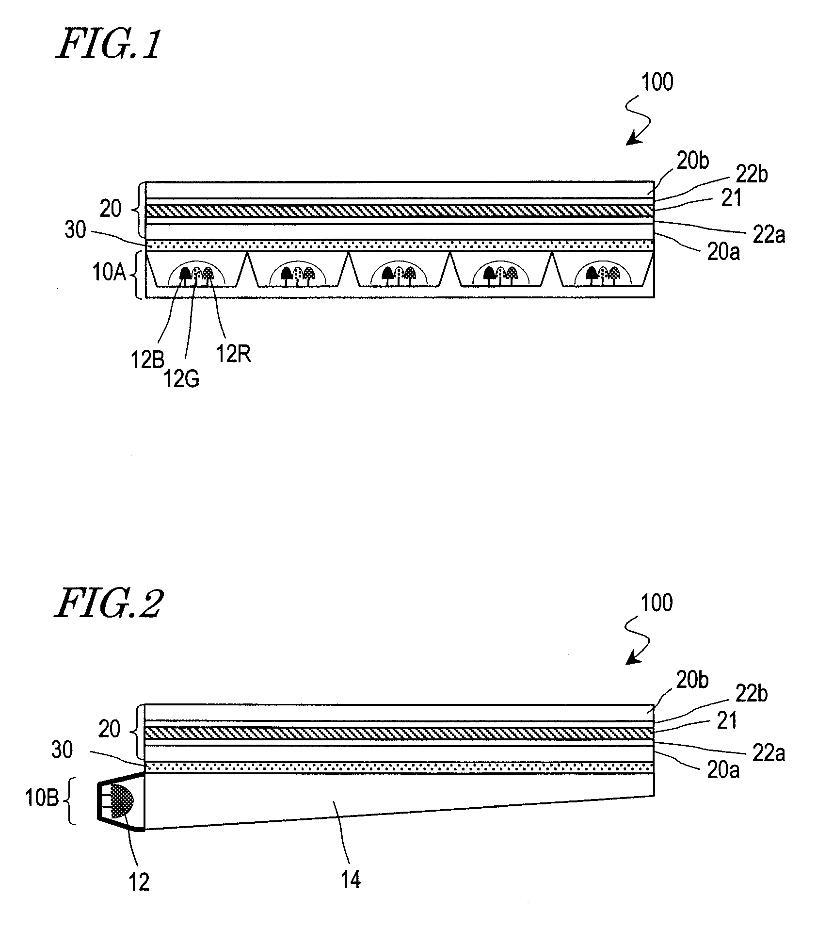
[0026]An illuminator comprised in an liquid crystal display device according to the present invention includes a light source causing primary generation of at least blue light, among other light which is used for displaying, and therefore deterioration of the photo-alignment film due to ultraviolet light is unlikely to occur. As a result, according to the present invention, the reliability of a liquid crystal display device incorporating a photo-alignment film can be improved, and thus a liquid crystal display device which is capable of performing high-quality displaying for long hours can be provided.

Problems solved by technology

However, when alignment films which have been subjected to a rubbing treatment are used, there are problems in that orientation defects may occur due to foreign matter which emerged during the rubbing, or switching elements (e.g., TFTs) which are provided on the substrate may be destroyed by the static electricity which is generated during the rubbing.
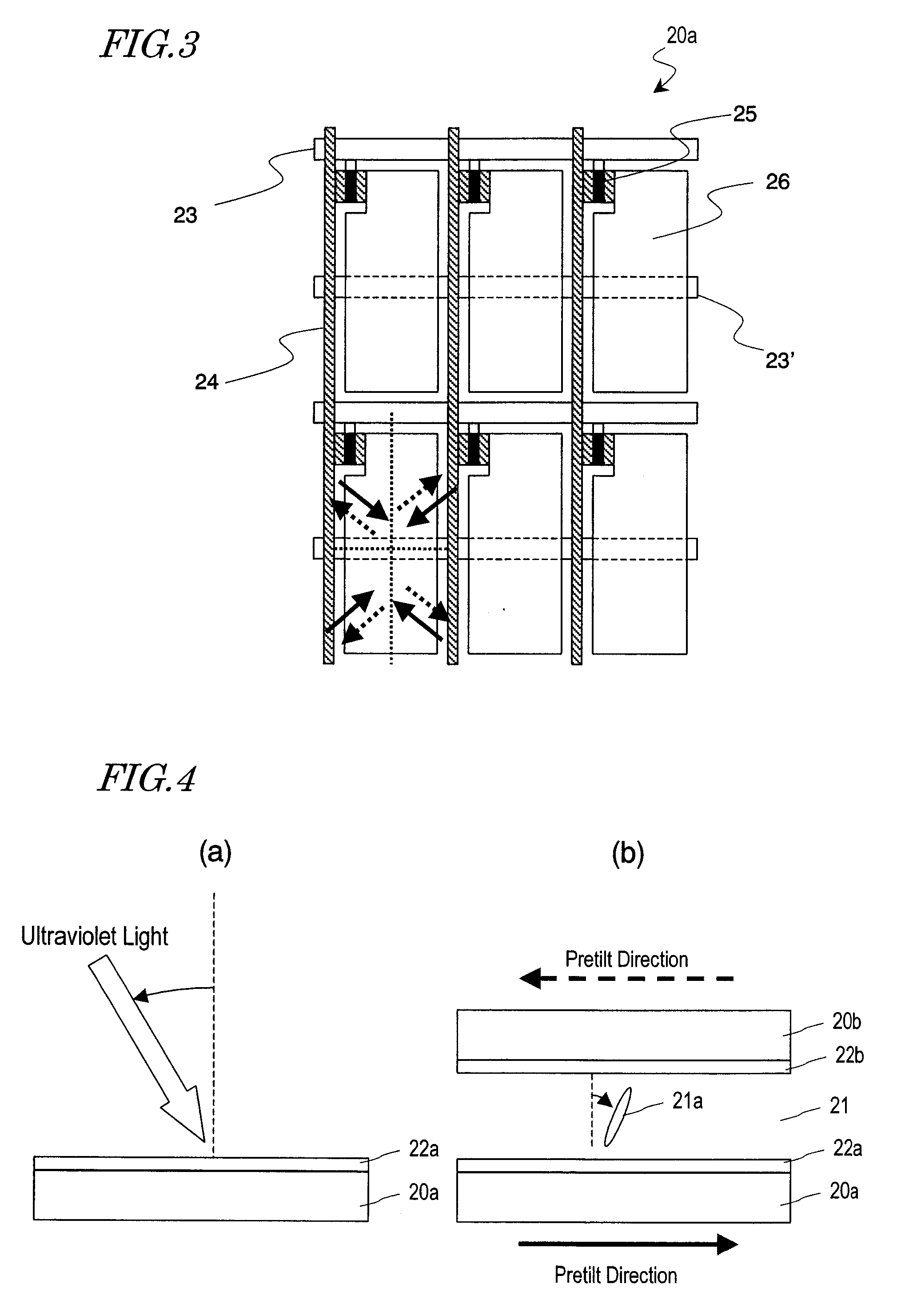
However, when a liquid crystal display device incorporating alignment films which have been imparted with an orientation regulating force through a photo-alignment treatment (hereinafter referred to as “photo-alignment films”) are used for long hours, the alignment may be disturbed or the voltage retention rate may be lowered.
Thus, a liquid crystal display device incorporating photo-alignment films lacks in reliability.

Method used


Image

  • Liquid crystal display device and electronic device using the same
  • Liquid crystal display device and electronic device using the same
  • Liquid crystal display device and electronic device using the same

Examples


Embodiment Construction

[0043]The inventor has conducted a detailed analysis of the causes for the aforementioned problems occurring in a liquid crystal display device comprising photo-alignment films. Being a non-emission type display device, a liquid crystal display device comprises an illuminator, and displaying is performed by modulating the light from the illuminator with a liquid crystal panel. The inventor has ascertained that a minute amount of ultraviolet light is emitted from the illuminator, and found that the ultraviolet light deteriorates the photo-alignment films, thus causing orientation disturbances and a decrease in the voltage retention rate.

[0044]In the illuminator of a commonly-used liquid crystal display device, a cold-cathode tube is used as a light source. In the cold-cathode tube, mercury which is enclosed within the tube is excited by discharging to generate ultraviolet light, and this ultraviolet light excites a phosphor which is enclosed in the tube, whereby visible light that is...


PUM


Abstract

A liquid crystal display device includes an illuminator and a liquid crystal panel for performing displaying by using light which is emitted from the illuminator. The liquid crystal panel includes a pair of substrates, a liquid crystal layer provided between the pair of substrates, and a pair of alignment films provided on sides of the pair of substrates facing the liquid crystal layer. At least one of the alignment films is a photo-alignment film which is imparted with an orientation regulating force through a photo-alignment treatment, and the illuminator includes a light source causing primary generation of at least blue light, among other light which is used for displaying.

Description

BACKGROUND OF THE INVENTION[0001]1. Field of the Invention[0002]The present invention relates to a liquid crystal display device, and in particular to a liquid crystal display device comprising an alignment film which has been imparted with an orientation regulating force through a photo-alignment treatment. Moreover, the present invention also relates to an electronic apparatus incorporating such a liquid crystal display device.[0003]2. Description of the Related Art[0004]In recent years, liquid crystal display devices have been used in OA devices such as personal computers and AV devices such as camcorders, on the strength of being thin and consuming little power.[0005]A liquid crystal display device performs displaying by utilizing optical anisotropy of liquid crystal molecules, and therefore the orientation directions of the liquid crystal molecules must be controlled with alignment films. As alignment films, films which are formed of a polymer material such as polyimide or poly...

Claims


Application Information

Patent Timeline
IPC IPC(8): G02F1/13357G02F1/13
CPCC09K19/18C09K19/322G02F1/133603G02F1/133617Y10T428/1036G02F1/134363G02F2001/133614G02F2201/086G02F1/133621G02F1/133788C09K2323/03G02F1/133614
Inventor MIYACHI, KOICHI
Owner SHARP KK
Learn More