Structure for diagnosis system of reaction process

Active Publication Date: 2009-02-19
KOREA RES INST OF STANDARDS & SCI
View PDF2 Cites 7 Cited by
  • Summary
  • Abstract
  • Description
  • Claims
  • Application Information

AI Technical Summary

Benefits of technology

[0007]It is an object of the present invention to provide a spectroscopy analyzer for real-time diagnostics of process, in which a spectroscopic analysis is performed in vacuum state, whereby i

Problems solved by technology

In the conventional spectroscopy analyzer, since the spectroscopic analysis is performed in an atmospheric state, it is difficult to exactly perform the spectroscopic analysis of the reaction byproduct or the reactant, and also since the reaction byproduct or the reactant is attached and deposited on an input window through which the beam is introduced, an output window through which the beam is output, a reflecting mirror and so on, the b

Method used


Image

  • Structure for diagnosis system of reaction process
  • Structure for diagnosis system of reaction process
  • Structure for diagnosis system of reaction process

Examples


Embodiment Construction

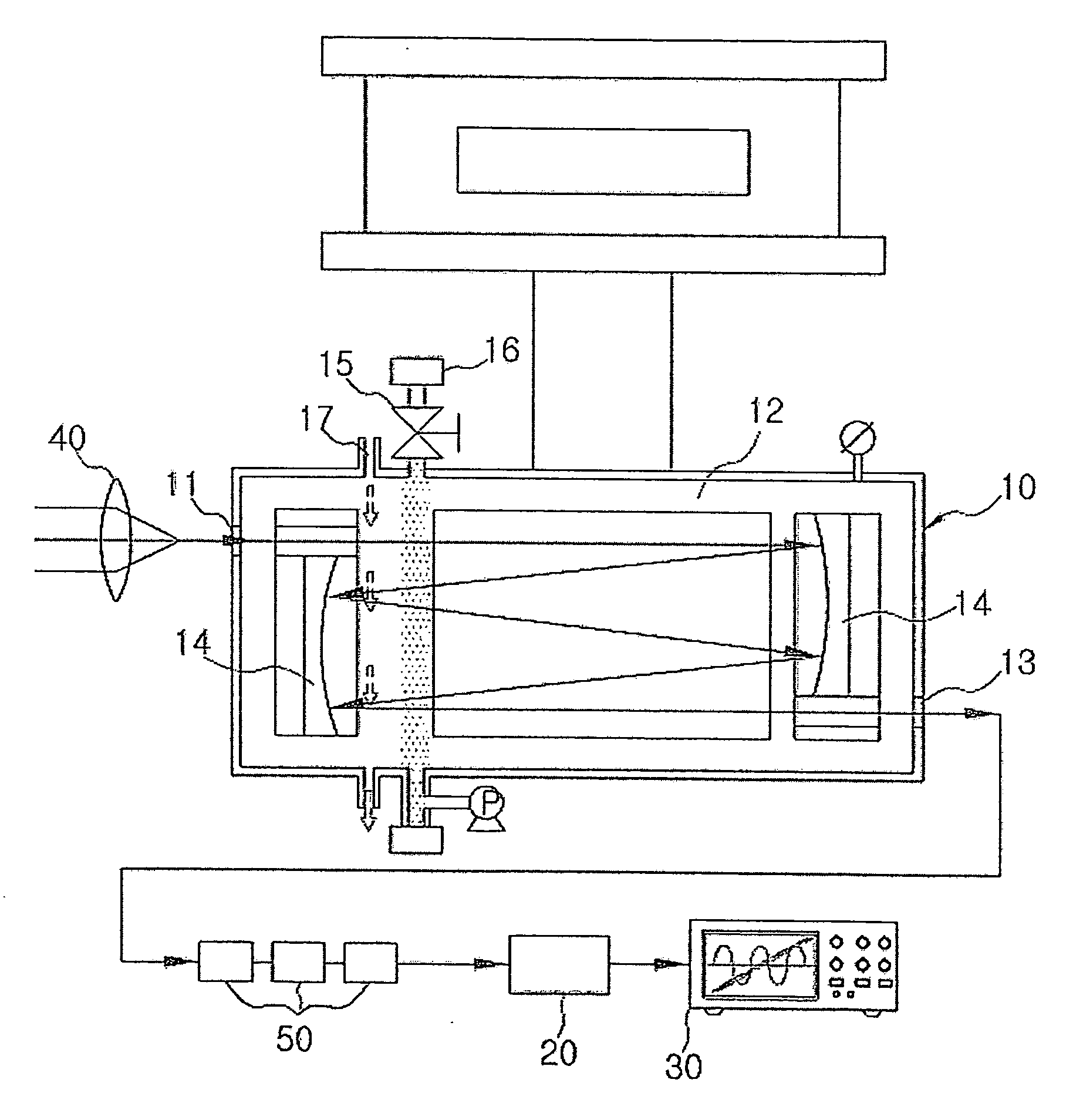
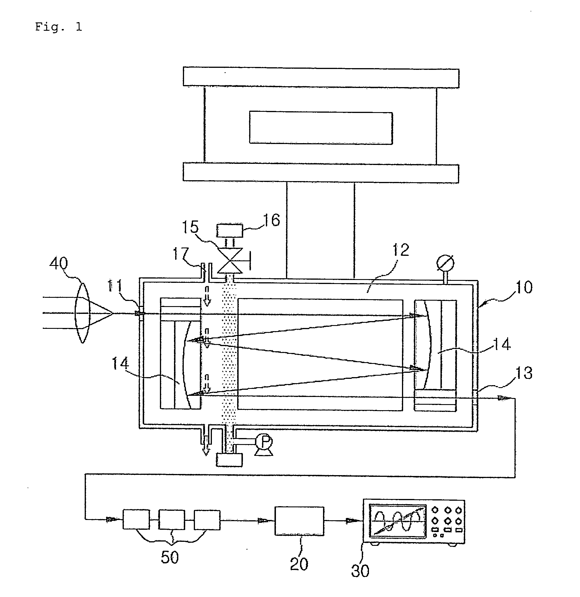
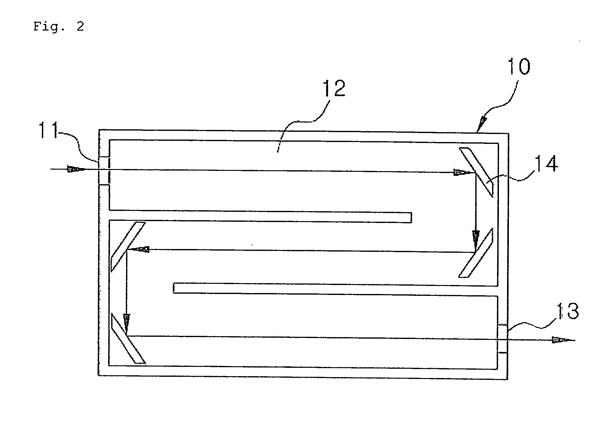
[0030]10, 110: reactor 11, 111: input window[0031]12, 112: receiving part 13, 116: output window[0032]14: reflecting mirror 15, 117: pressure controller[0033]16: air curtain 17, 119: injecting port[0034]20, 120: detector 30, 130: analyzer[0035]113: fixing part 114: crystal[0036]115: plasma electrode 118: cleaning port[0037]1110: first gas receiving part[0038]1111: gas receiving part input window[0039]1113: length adjuster[0040]1120: second gas receiving part[0041]1122: gas receiving part output window[0042]1123: length adjuster[0043]1130: reactor 1131: input window[0044]1132: output window[0045]1150: gas supplying part[0046]1151: gas inlet valve[0047]1154: temperature control part[0048]1160: pump 1162: gas outlet valve[0049]1200: infrared ray emitting unit[0050]1300: infrared ray receiving unit[0051]1400: calculating unit[0052]1110a: first gas receiving part[0053]1111a: gas receiving part input window[0054]1120a: second gas receiving part[0055]1222a: gas receiving part output window...


PUM


Abstract

The present invention relates to a spectroscopy analyzer for real-time diagnostics of process, and more particularly, to a spectroscopy analyzer for real-time diagnostics of process, in which a beam is injected to a reaction byproduct or a reactant and then an output beam is measured, thereby performing quantitative and qualitative analysis of the reaction byproduct or the reactant.

Description

TECHNICAL FIELD[0001]The present invention relates to a spectroscopy analyzer for real-time diagnostics of process, and more particularly, to a spectroscopy analyzer for real-time diagnostics of process, in which a beam is injected to a reaction byproduct or a reactant and then an output beam is measured, thereby performing quantitative and qualitative analysis of the reaction byproduct or the reactant.BACKGROUND ART[0002]Every atom or molecule moves continuously within a space, and also includes energy corresponding to such movement. Since the energy associated with the movement of the atom or molecule is quantized, the energy can be existed only in a certain energy state. The atom or molecule which moves in the certain energy state may absorb energy from the outside and thus be excited to a high energy state. The energy can be expressed as follows: E=hv, wherein h is Planck's constant and v is a frequency. Therefore, the energy necessary to be excited to a higher energy state can ...

Claims


Application Information

Patent Timeline
IPC IPC(8): G01N21/25G01N21/15G01N21/35G01N21/3504G01N21/3581G01N21/75
CPCG01N21/031G01N2021/151G01N21/3504
Inventor KANG, SANG WOOYUN, JU YOUNGSEONG, DAE JINSHIN, YONG HYEON
Owner KOREA RES INST OF STANDARDS & SCI
Why Eureka
Try Eureka