Gain-clamped optical amplifying apparatus using fiber raman amplifier having raman cavity

a technology of optical amplifier and amplifier, which is applied in the direction of lasers, electromagnetic transmission, transmission, etc., can solve the problems of deteriorating data communication quality, increasing the bit error rate of optical communication,

Inactive Publication Date: 2009-02-19
ELECTRONICS & TELECOMM RES INST
View PDF6 Cites 13 Cited by
  • Summary
  • Abstract
  • Description
  • Claims
  • Application Information

AI Technical Summary

Benefits of technology

[0019]The present invention provides a method of achieving all-optical gain-clamped amplificat

Problems solved by technology

This characteristic increases a bit error rate in an optical

Method used


Image

  • Gain-clamped optical amplifying apparatus using fiber raman amplifier having raman cavity
  • Gain-clamped optical amplifying apparatus using fiber raman amplifier having raman cavity
  • Gain-clamped optical amplifying apparatus using fiber raman amplifier having raman cavity

Examples


Embodiment Construction

[0045]The present invention will be described in detail by explaining embodiments of the invention with reference to the attached drawings.

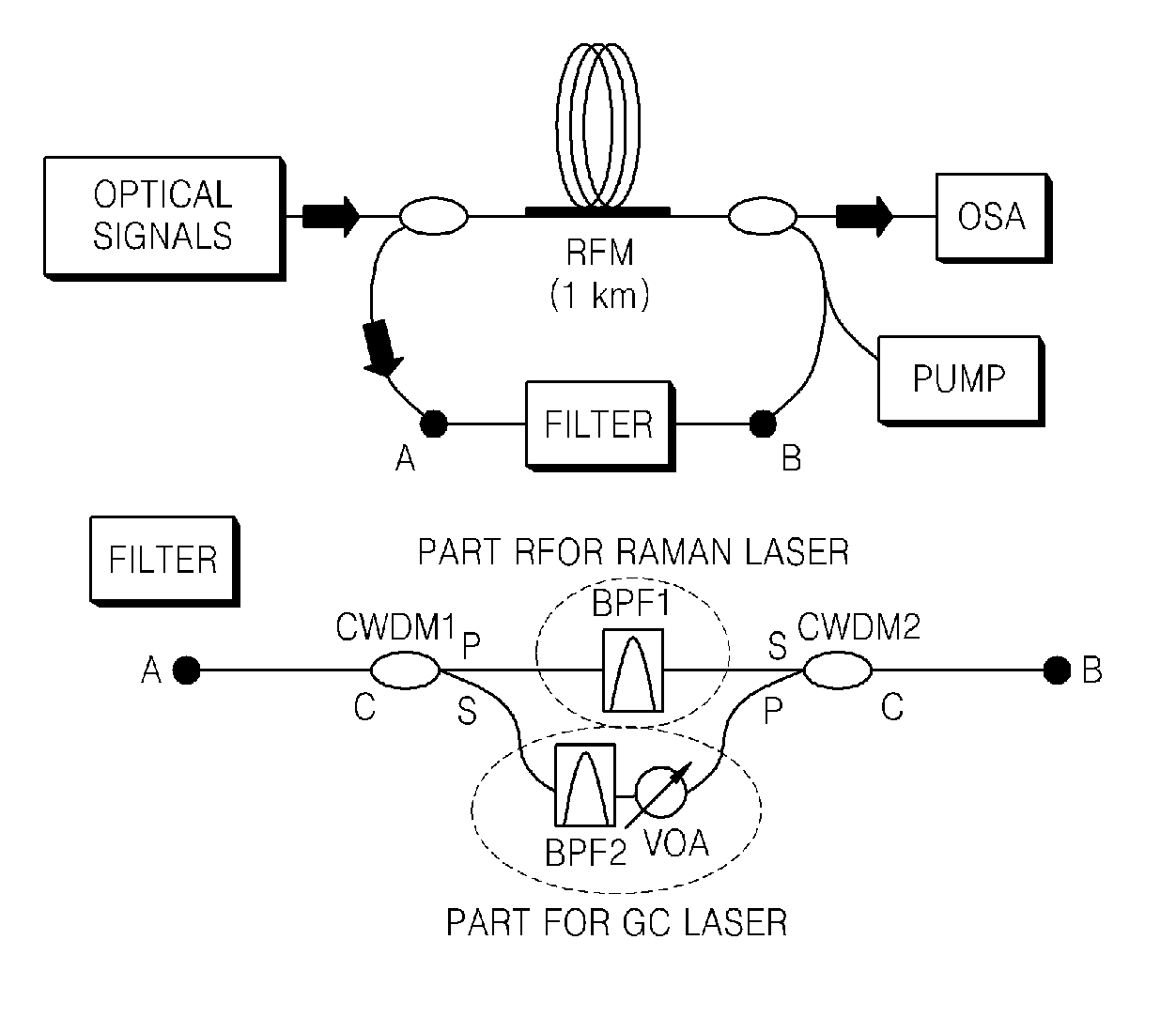
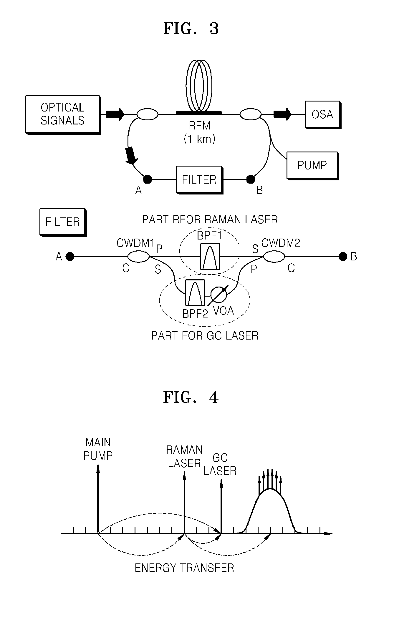
[0046]FIG. 3 is a schematic block diagram illustrating an optical amplifier achieving gain clamping in an optical amplifier having a Raman cavity, according to an embodiment of the present invention.

[0047]Referring to FIG. 3, a Raman fiber of 1 Km is used as a Raman fiber module (RFM). The RFM amplifies input optical signals by a Raman gain and then outputs the amplified optical signal to an output terminal.

[0048]The pump uses a backward pumping scheme for a signal direction so that relative intensity noise (RIN), which is a temporal dithering effect of a pump beam, does not affect the input optical signal.

[0049]A feedback loop is formed between the input terminal and the output terminal, thereby forming a resonant cavity to generate a Raman laser and a gain clamping laser (GC laser).

[0050]Light from the pump causes stimulated Raman scattering (S...


PUM


Abstract

Provided is a gain-clamped (GC) optical amplifier using a fiber Raman amplifier (FRA) having a Raman cavity. The FRA having a Raman cavity comprises a Raman fiber module (RFM) amplifying and outputting an input optical signal and a resonant cavity generating a Raman laser and a gain clamping laser (GC laser), wherein the resonant cavity is formed as a feedback loop between an input terminal and an output terminal of the RFM. Accordingly, a gain of an optical signal propagating along a core of RFM keeps a constant value regardless of input signal intensity by generating the GC laser for gain clamping between a wavelength band of the Raman laser and a gain band of input signals.

Description

CROSS-REFERENCE TO RELATED PATENT APPLICATION[0001]This application claims the benefit of Korean Patent Application No. 10-2007-0059100, filed on Jun. 15, 2007, in the Korean Intellectual Property Office, the disclosure of which is incorporated herein in its entirety by reference.BACKGROUND OF THE INVENTION[0002]1. Field of the Invention[0003]The present invention relates to a gain-clamped optical amplifier, and more particularly, to a gain-clamped optical amplifier using an all-optical method in an optical amplifier structure having a Raman cavity, without any loss of bandwidth.[0004]2. Description of the Related Art[0005]Much research has been conducted on fiber Raman amplifiers (FRAs), which are capable of amplifying optical signals having a wavelength band that cannot be amplified with an erbium-doped fiber amplifier (EDFA), and which are able to improve the performance of the EDFA.[0006]Fiber Raman amplification has advantages in that an amplification bandwidth of an FRA can be...

Claims


Application Information

Patent Timeline
IPC IPC(8): H01S3/00
CPCH01S3/0675H01S3/06754H01S3/06791H01S3/302H01S3/106H01S3/1302H01S3/08027H01S3/30
Inventor SEO, HONG-SEOKAHN, JOON TAEPARK, BONG JECHUNG, WOON JIN
Owner ELECTRONICS & TELECOMM RES INST
Why Eureka
Try Eureka