
Multiple spur multiple spiral groove twist drill

a multi-spiral groove, twisting drill technology, applied in the direction of twisting drills, wood boring tools, manufacturing tools, etc., can solve the problems of limited operation efficacy, affecting the schedule of drilling tasks, poor etc., to increase the overall structural strength of the drill and increase the cutting section strength

Inactive Publication Date: 2009-02-19
LIAO CHUNG LIANG +1
View PDF4 Cites 16 Cited by
  • Summary
  • Abstract
  • Description
  • Claims
  • Application Information

AI Technical Summary

Benefits of technology

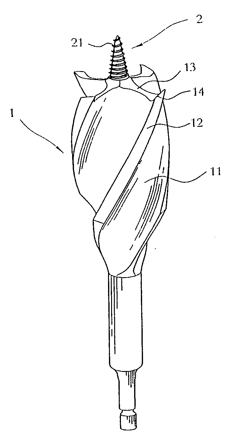
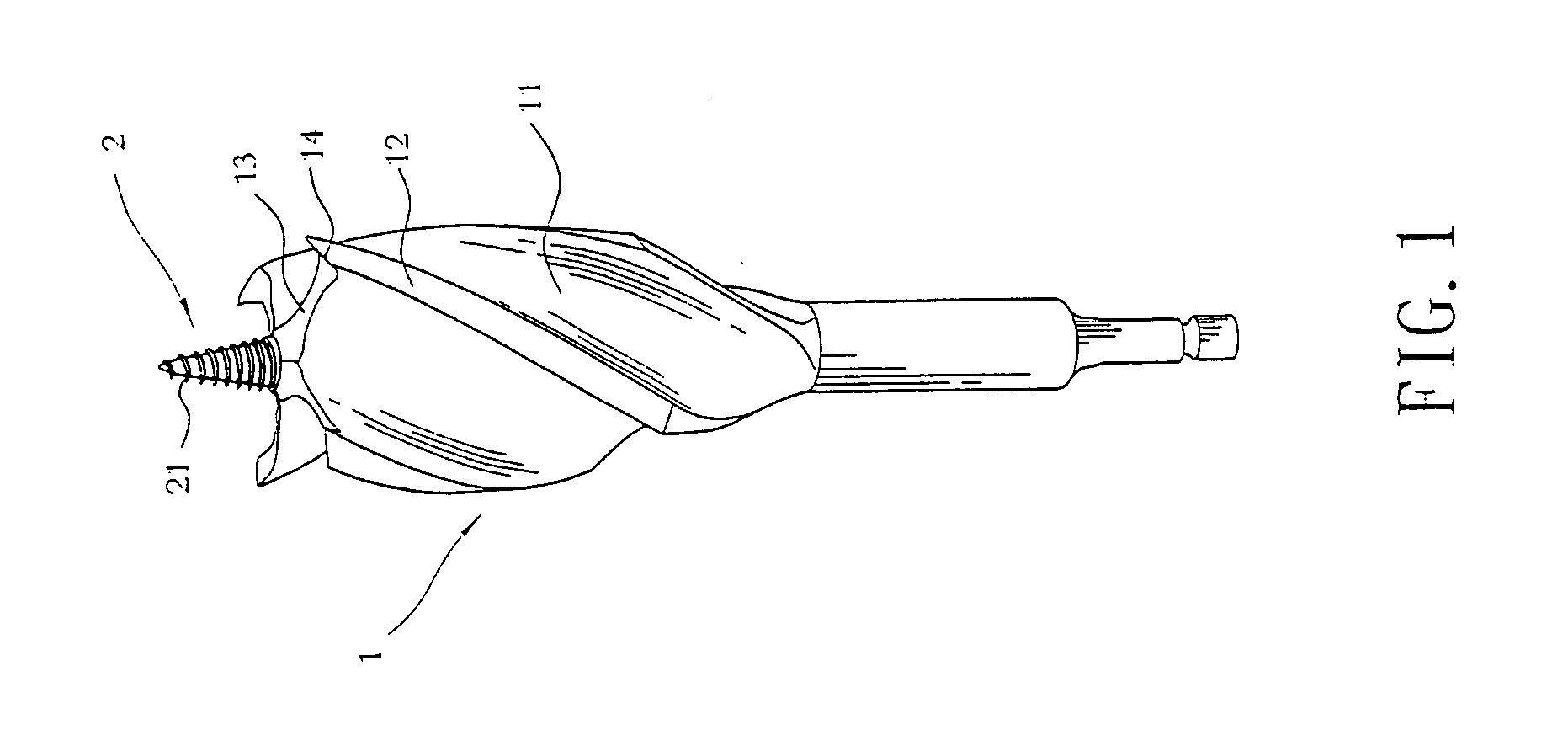
[0004]The primary purpose of the present invention is to provide a MULTIPLE SPUR MULTIPLE SPIRAL GROOVE TWIST DRILL comprised of a flute and an inwardly formed spiral; and a spur is formed at where the flute and a cutting section crossing each other for the drill to be of industrial utility and cost benefits.
[0006]In practice, increased strength for the cutting section by the spur in conjunction with the flute groove and the flute land upgrades the overall structural strength of the drill.

Problems solved by technology

However, each tip disposed on the edge on both sides of the front of the spade portion of the prior art indicates a tapered end surface, and designed as a flat and thin tip by compromising the spade portion, leading to poor strength of the overall structure of the drill.
The tip could easily get broken and damaged when contacting any hard matter hidden in the wooden work piece, leading to affected the schedule of drilling task, limited operation efficacy, and the waste of operation cost.

Method used


Image

  • Multiple spur multiple spiral groove twist drill
  • Multiple spur multiple spiral groove twist drill
  • Multiple spur multiple spiral groove twist drill

Examples


Embodiment Construction

[0012]Referring to FIGS. 1 and 2, a MULTIPLE SPUR MULTIPLE SPIRAL GROOVE TWIST DRILL of the present invention is comprised of a flute (1), whose shank is clamped and secured to a tooling holder of a drilling machine, containing multiple, and four is preferred, spiral flute grooves (11); a cutting section (13) is provided to a front of the flute land (12); a spur (14) is disposed is formed at where the cutting section (13) and the flute (12) crossing each other; and a lead screw point (2) disposed at a center on a front of the flute (1) is provided with a tapered thread (21) to provide the MULTIPLE SPUR MULTIPLE SPIRAL GROOVE TWIST DRILL for drilling a wooden work piece.

[0013]The spiral flute groove (11) is designed with a spiral angle θ that is reduced to 30° for increasing drilling power in feeding the drill.

[0014]The flute land (12) is itself formed inwardly as flute grooves (11) to provide support and upgrade cutting torque for the flute land (12).

[0015]The sharp spur (14) dispos...


PUM

PropertyMeasurementUnit
spiral angleaaaaaaaaaa
drilling strengthaaaaaaaaaa
strengthaaaaaaaaaa

Abstract

A MULTIPLE SPUR MULTIPLE SPIRAL GROOVE TWIST DRILL includes a flute, whose shank is clamped and secured to a tooling holder of a drilling machine and contains multiple spiral flute grooves; each flute groove is disposed on its peripheral a flute land, a cutting section is formed on a front tip of the flute land; a spur formed at where the cutting section and the flute land crossing each other; and a lead screw point with tapered thread being disposed at a center on the front of the flute to increase strength of the cutting section; and the flute groove in conjunction with the flute to fortify the overall structural strength to provide longer service life and cost benefits of the drill.

Description

FIELD OF THE INVENTION[0001]The present invention is related to a MULTIPLE SPUR MULTIPLE SPIRAL GROOVE TWIST DRILL, and more particularly, to an improved construction of a spade bit that provides prolonged service life and cost efficiency.BACKGROUND OF THE INVENTION[0002]Whereas wooden materials usually have to undergo scraping, planning, sawing, cutting, and / or drilling processes for assembly before becoming a finished product as designed; as illustrated in FIG. 5 of the accompanying drawings for a perspective view of a front of a spade bit (3) of the prior art, it is comprised of a spade portion (31) and a lead TIP(32); a corner tip (311) is disposed on the peripheral of both sides at the front of the spade portion (31); to start the process, a comparatively small hole is drilled on a designated wooden work piece to lead smooth guiding for initial cutting. Once the spade bit enters into a surface layer of the work piece, followed with further cutting using the both corner tips (31...

Claims


Application Information

Patent Timeline
Patent Type & Authority Applications(United States)
IPC IPC(8): B23B51/02
CPCY10T408/9097B27G15/00B23B51/02
Inventor LIAO, CHUNG LIANGLIAO, CHUNG-HUNG
Owner LIAO CHUNG LIANG
Learn More