Gasification reactor

Active Publication Date: 2009-02-26
AIR PROD & CHEM INC
View PDF7 Cites 14 Cited by
  • Summary
  • Abstract
  • Description
  • Claims
  • Application Information

AI Technical Summary

Benefits of technology

[0010]The present invention provides a gasification reactor comprising a pressure shell, a reaction zone partly bounded by a vertically oriented tubular membrane wall, a horizontally directed burner having a burner head at which, said burner protruding into the vertical wall part of the membrane wall via a burner muffle, said burner muffle comprising several vertically oriented, concentric and interconnected rings, wherein successive rings have an increasing

Problems solved by technology

It has been found that with increasing gas pressures and reduced reactor diameter, slag ingresses into the burner muffles.
This slag deflects the oxygen/coal flame towards the metallic muffle walls, which causes extremely high heat fluxes.
In combination with the higher overall surface temperatures steam blankets can be formed on the water cooling side, resulting in that locally no adequate cooling exists.
This in turn may result in that at such

Method used


Image

  • Gasification reactor
  • Gasification reactor
  • Gasification reactor

Examples


Example

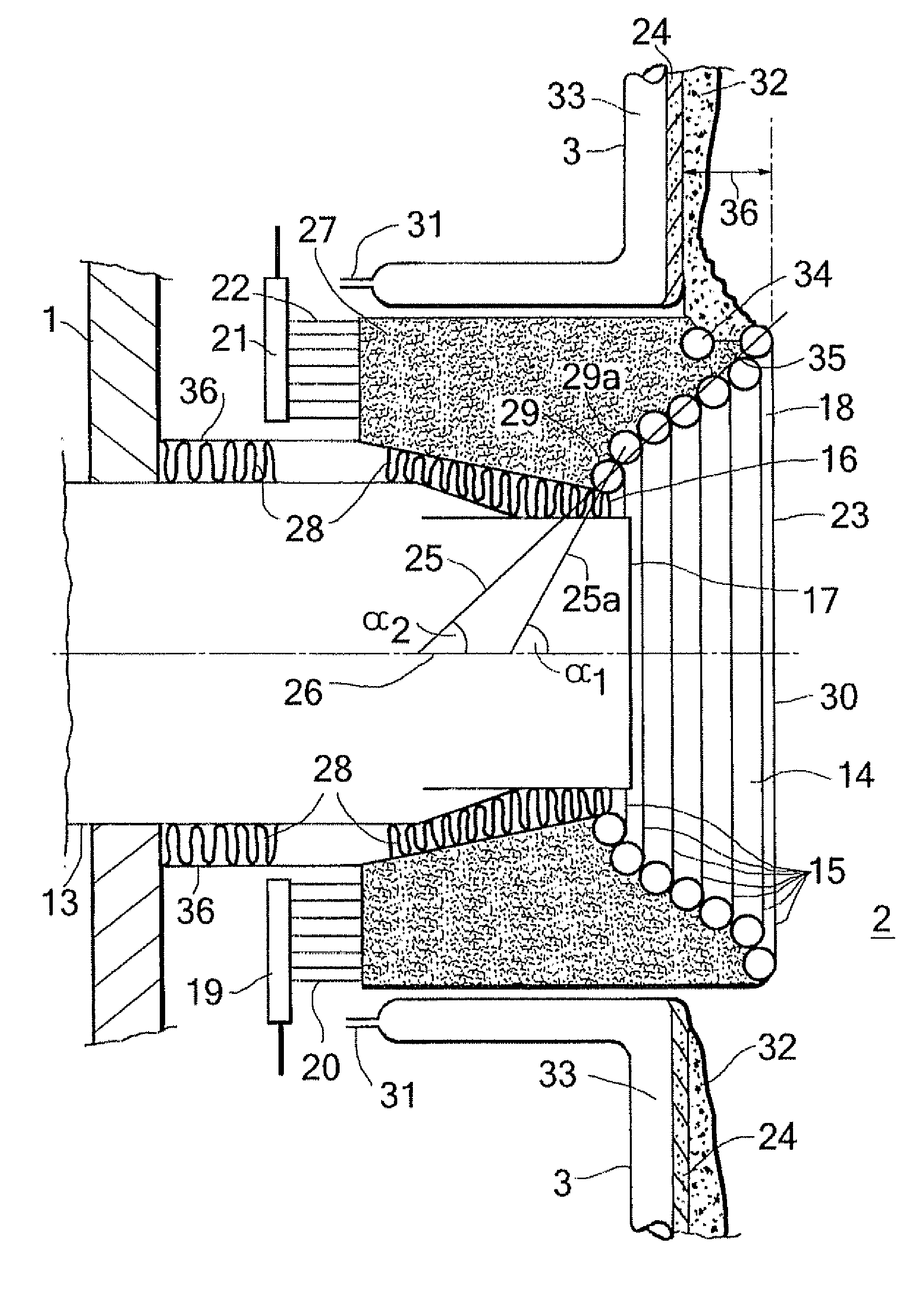
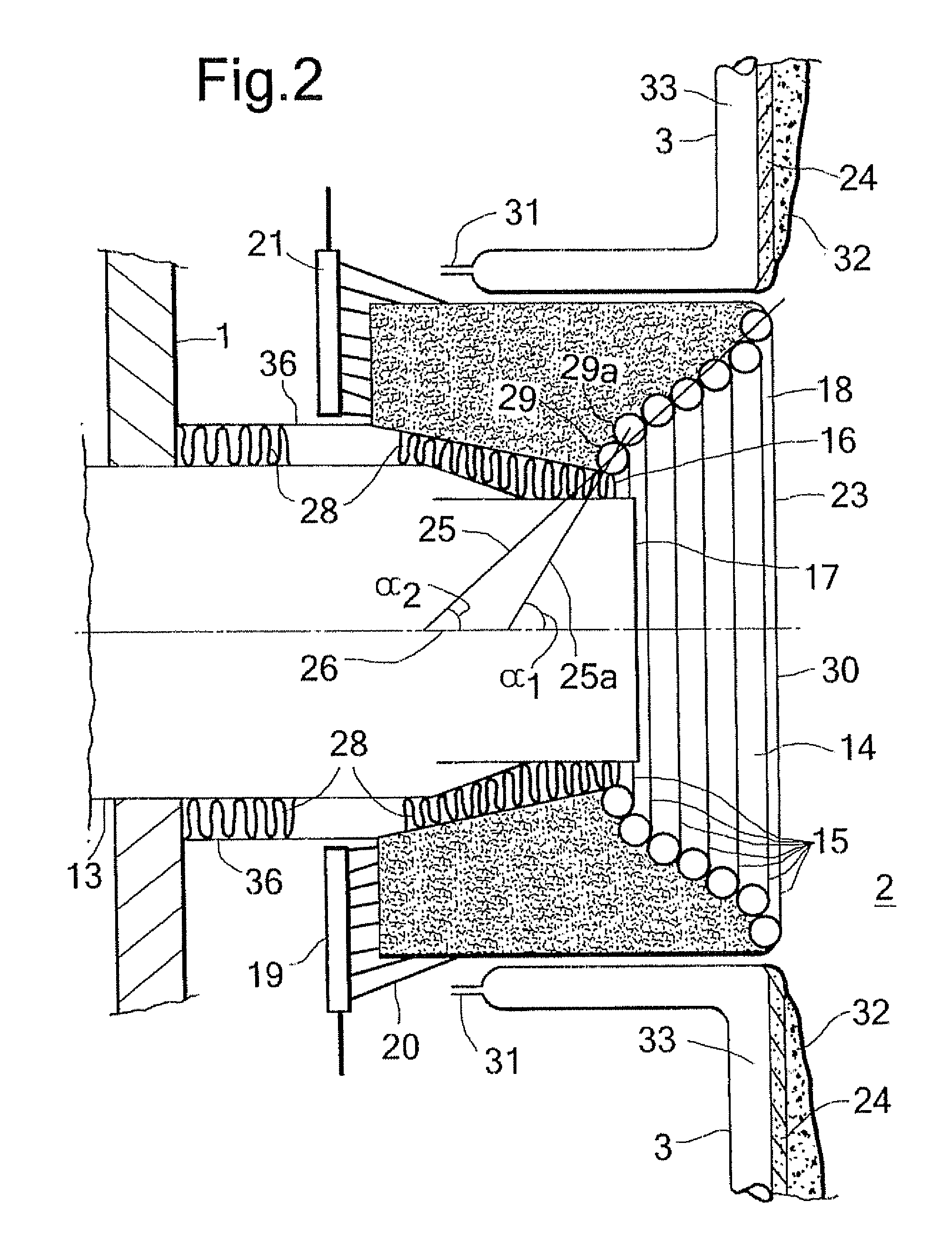
[0014]Applicants have found that by providing adequate cooling to the surfaces of the burner muffle as achieved by the claimed gasification reactor a robust design is obtained which can also operate at the higher gasification pressures, preferably at a pressure of above 30 bar, more preferably at a pressure of above 35 bar and below 70 bar. Applicants have further found that the protrusion is beneficial to avoid slag from entering the burner muffle. It is believed that by avoiding slag from depositing on the surface of the muffle lower local heat fluxes occur and thus an even more robust design is obtained.

[0015]Additionally, it has been found that the operational temperature range for a gasification reactor for a specific ash containing feedstock can be widened by using the protruding burner muffle. This is beneficial in two ways: a) the operation of the gasification reactor is easier, safer and more reliable and b) by operating at the lower range of the widened operating window th...


PUM


Abstract

A gasification reactor comprising a pressure shell, a reaction zone partly bounded by a vertically oriented tubular membrane wall, a horizontally directed burner having a burner head at which, in use, a combustion flame is discharged into said reaction zone, said burner protruding into the vertical wall part of the membrane wall via a burner muffle, said burner muffle comprising several vertically oriented, concentric and interconnected rings, wherein each successive ring has an increasing diameter relative to the preceding ring resulting in that the burner muffle has a muffle opening for the burner head at one end and a larger opening at its other—flame discharge—end, the rings comprising a conduit having an inlet end for a cooling medium and an outlet for used cooling medium and wherein the muffle opening for the burner head is located between the pressure shell and the membrane wall and wherein the burner muffle protrudes into the reaction zone.

Description

[0001]This application claims the benefit of European Application EP 07100650.6 filed Jan. 17, 2007 and U.S. Provisional Application No. 60 / 887103 filed Jan. 29, 2007.BACKGROUND OF THE INVENTION [0002]The invention is directed to a gasification reactor comprising a pressure shell, a reaction zone partly bounded by a vertically oriented tubular membrane wall, a horizontally directed burner having a burner head at which, in use, a combustion flame is discharged into said reaction zone, said burner protruding into the vertical wall part of the membrane wall via a burner muffle.[0003]Such a gasification reactor is described in U.S. Pat. No. 4,202,672. This publication describes a coal gasification reactor provided with a pressure shell, a reaction zone and a membrane wall, which partly defines the reaction zone. The tubular shaped membrane wall comprises interconnected conduits in which evaporating cooling water is present.[0004]In U.S. Pat. No. 4,959,080 a coal gasification process is ...

Claims


Application Information

Patent Timeline
IPC IPC(8): C10J3/68C10J1/207
CPCC10J3/485C10J3/76C10J3/78C10J2300/1223C10J2300/0916C10J2300/092C10J2300/093C10J2200/09C10J3/48C10J3/20
Inventor VON KOSSAK-GLOWCZEWSKI, THOMAS PAULVAN SCHIE, HENRICUS GIJSBERTUSSCHILDER, JOHANNES GERARDUS MARIA
Owner AIR PROD & CHEM INC
Why Eureka
Try Eureka