Axle Cooling Using Hydraulic Return Oil

Active Publication Date: 2009-02-26
BLUE LEAF I P
View PDF21 Cites 5 Cited by
  • Summary
  • Abstract
  • Description
  • Claims
  • Application Information

AI Technical Summary

Benefits of technology

[0011]An advantage of the present invention is the apparatus provides cooling to the lubricating oil of the axle brakes, making use of existing fan and pump components.

Problems solved by technology

When this is done frequently, the brakes become overheated.
In some instances, however, convection to and from the axle housing surfaces is insufficient to remove braking heat rapidly enough, and the axle lubricant consequently becomes excessively hot (e.g., above 300 degrees Fahrenheit).
The axle shaft and axle housing are of limited size and mass and, hence, of limited heat capacity.
However, in extremely cold operating conditions, especially during start-up, it may be undesirable to attempt to circulate the lubricating oil to the axle assembly.
Such circulation of highly viscous lubricating oil may result in the formation of “hot spots” in the axle assembly, causing degradation of axle assembly components.

Method used


Image

  • Axle Cooling Using Hydraulic Return Oil
  • Axle Cooling Using Hydraulic Return Oil
  • Axle Cooling Using Hydraulic Return Oil

Examples


Embodiment Construction

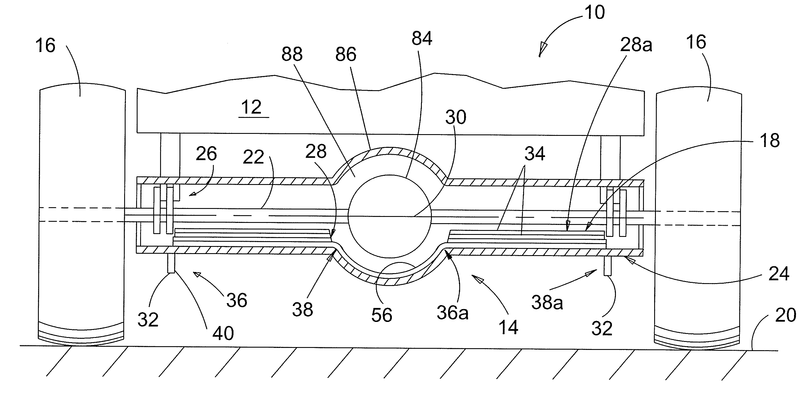
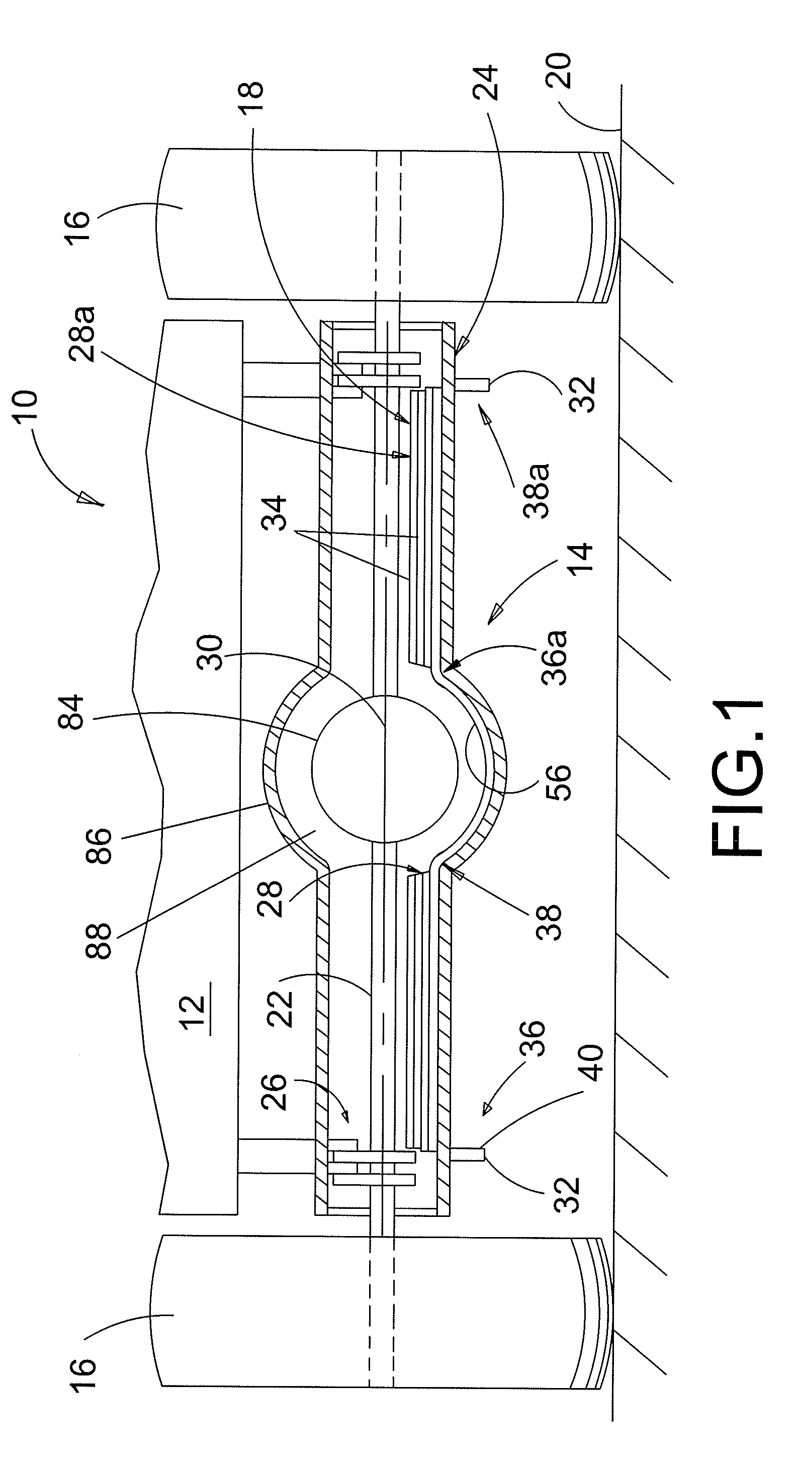
[0018]FIG. 1 shows a work vehicle 10 provided with a frame 12, an axle assembly 14, wheels 16, and an axle cooling apparatus 18. Frame 12 may be of any of the conventional types including fabricated steel or cast iron. Axle assembly 14 and axle cooling apparatus 18 are described below, and wheel 16 may be of any of the conventional types; e.g., rubber-tired, cleated, or tracked. Wheels 16 support axle assembly 14 with respect to a pavement or ground surface 20, and axle assembly 14 supports frame 12. Only one axle assembly 14 is shown, but work vehicle 10 may include any number of axle assemblies 14.

[0019]Axle assembly 14 includes at least one axle shaft 22 generally contained within an axle housing 24 and supported by axle housing 24 for rotative movement relative to axle housing 24. Axle shaft 22 is of conventional construction, typically machined of a medium-carbon steel and hardened at least in the regions of splines (not shown). Axle housing 24 is also generally of conventional...


PUM


Abstract

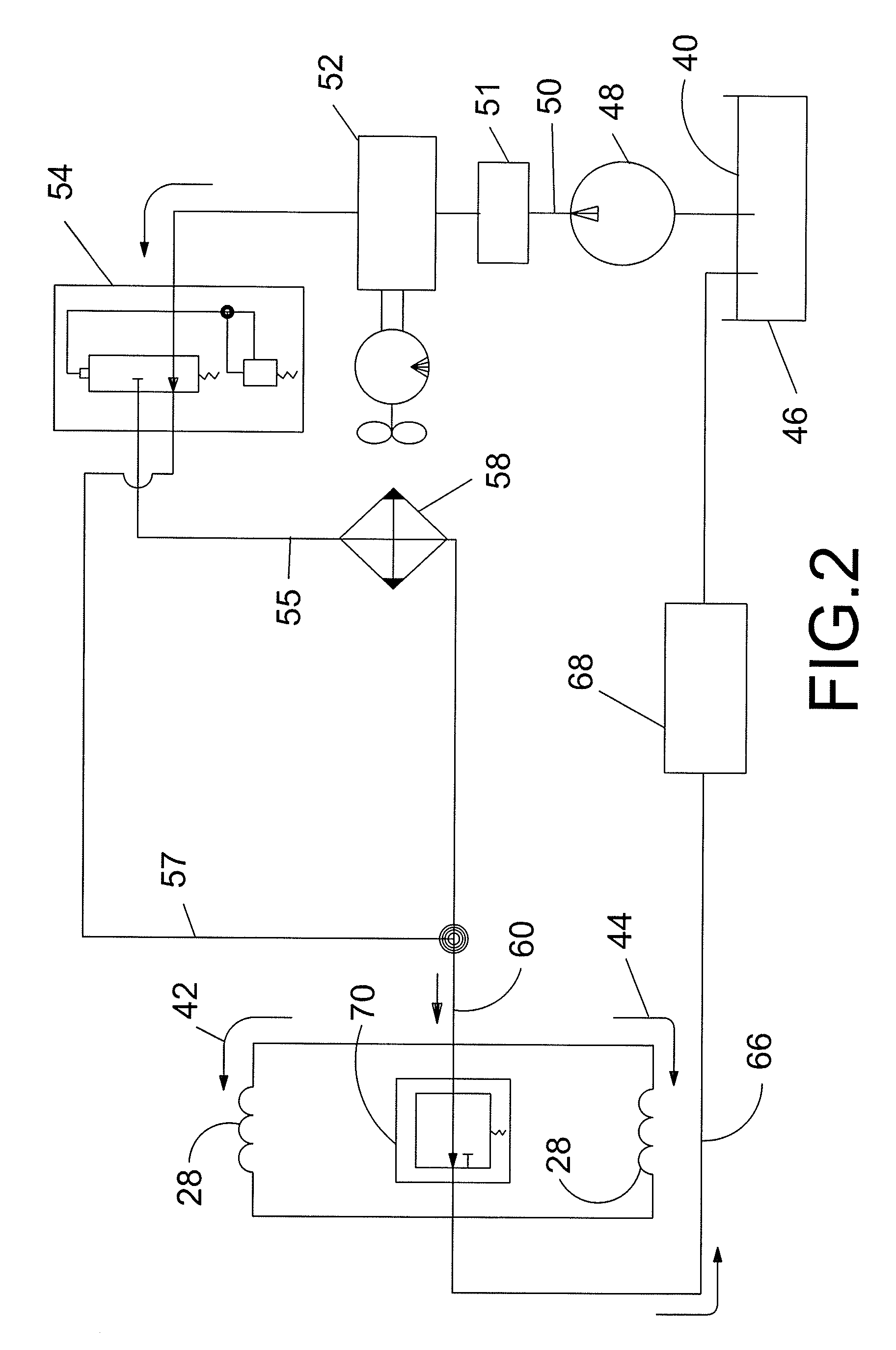
A work vehicle includes a frame and an axle assembly coupled to the frame, including a first axle shaft and coil substantially disposed in an axle housing. A first wheel couples to the first axle shaft of the axle assembly. An axle lubricating fluid is disposed within the axle housing. A cooling circuit fluidly coupled to the axle assembly circulates cooling fluid therethrough. The coil conducts cooling fluid through the first axle housing separately from the lubricating fluid. A cooling fluid circuit is selectively fluidly coupled to the first coil to circulate the cooling fluid therethrough.

Description

FIELD OF THE INVENTION[0001]The present invention relates generally to the field of work vehicles. It relates more particularly to removal of braking heat from an axle of a wheeled loader.BACKGROUND OF THE INVENTION[0002]Some work vehicles, such as end loaders, must change their directions of movement frequently. To do this, wheel or live axle brakes are generally used to first bring the vehicle to a stop. When this is done frequently, the brakes become overheated.[0003]This has sometimes been resolved by placing the brakes inside an axle housing, where the heat generated by brake friction is removed from the brake by an axle lubricating bath. The lubricant spreads the heat over the entire interior surface of the axle housing, whereupon thermal conduction through the walls of the axle housing heat the exterior surface of the axle housing and provide increased surface area for heat to be convected away by ambient air.[0004]In some instances, however, convection to and from the axle h...

Claims


Application Information

Patent Timeline
IPC IPC(8): F16D65/78B60H1/00F16H57/04F16N7/12
CPCB60B2310/303B60B2900/513B60B2360/104F16H57/0412Y10T74/2189B60B2360/147B60B2360/10B60B35/16B60B35/12B60B2310/302F16D65/78B60B2360/102
Inventor BARES, MICHAEL SYLVESTERLEMIRE, JARRODROEBER, JEFFREY ALAN
Owner BLUE LEAF I P
Why Eureka
Try Eureka