Loop Recording With Book Marking

a technology of loop recording and book marking, which is applied in the field of video camera recording technology, can solve the problems of vanman not distinguishing or diffencing any data, inconvenience and inflexibility of recording on the go, and the memory runs out too soon

Active Publication Date: 2009-02-26
STELLAR
View PDF6 Cites 47 Cited by
  • Summary
  • Abstract
  • Description
  • Claims
  • Application Information

AI Technical Summary

Benefits of technology

[0013]Since the surveillance apparatus is typically too small to house a large amount of memory, the surveillance apparatus also preferably has a wireless transmitter that is also functionally connected to the local memory. A sending facility uses the wireless transmitter to transmit write-protected portions of the circular buffer to a remote memory that is not physically connected to the local memory in some way. For example, the wireless transmitter could send write-protected portions of the circular buffer to a mobile phone, or the surveillance apparatus could be plugged into a mobile phone which is then used as a wireless transmitter to forward a write-protected portion to another remote memory. In a preferred embodiment, after a write-protected portion of the circular buffer is transferred to a remote memory, the protecting facility could remove the corresponding portion from protection so that the recording facility could use that portion to record data.

Problems solved by technology

One of the major shortcomings of the existing camcorder technology is that the memory runs out too soon.
This creates inconvenience and inflexibility for recording on the go.
However, Vanman does not distinguish or differentiate any data that is of importance.
Such transfers are processor intensive and may not be possible when the central office is out of range or an empty DVD disc is unavailable.
Mann also discusses streaming the images directly to a wireless memory that may have a larger capacity; however, this means that the camera does not work in the absence of a wireless connection.
However, Hattori fails to address sending data to a remote memory.

Method used


Image

  • Loop Recording With Book Marking
  • Loop Recording With Book Marking
  • Loop Recording With Book Marking

Examples


Embodiment Construction

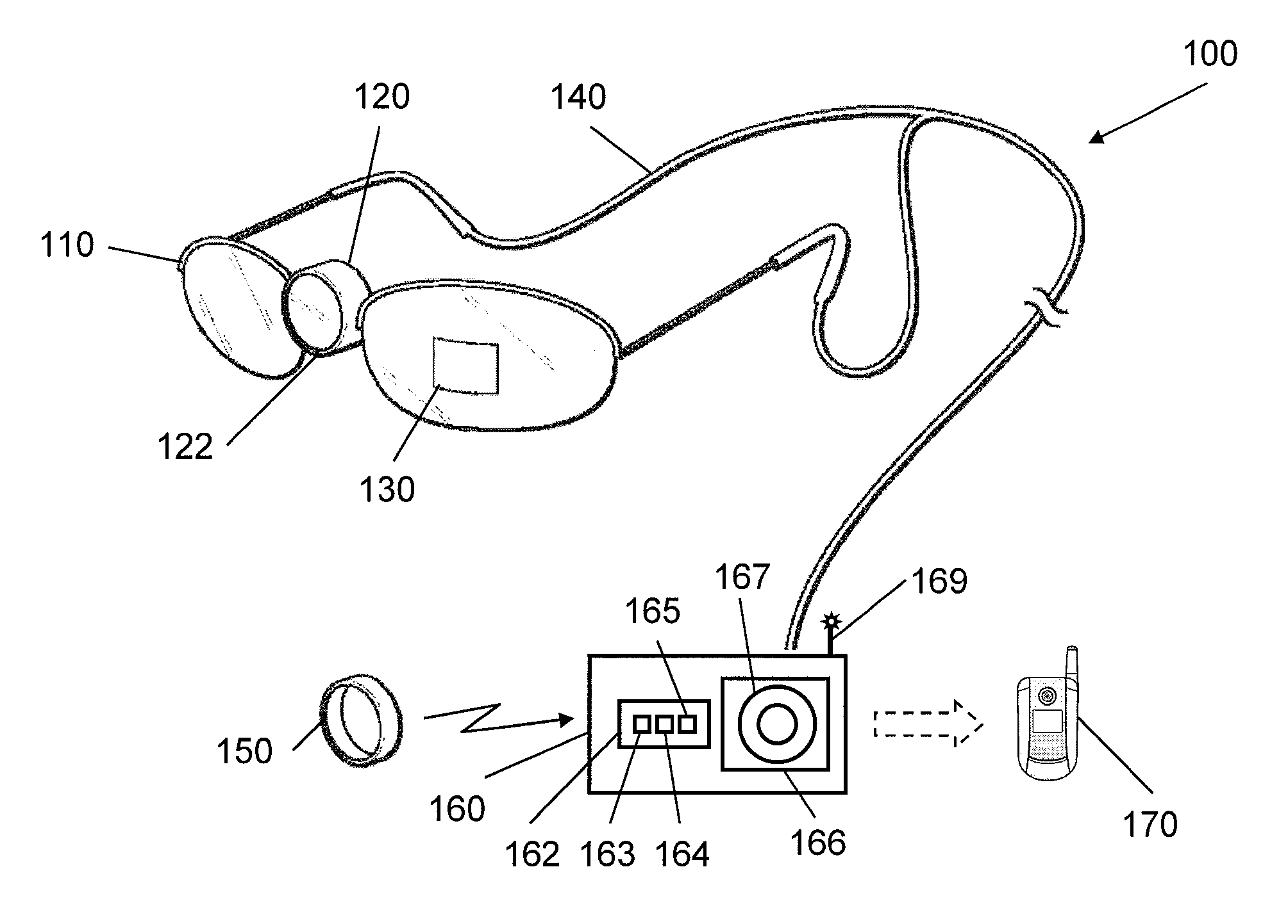
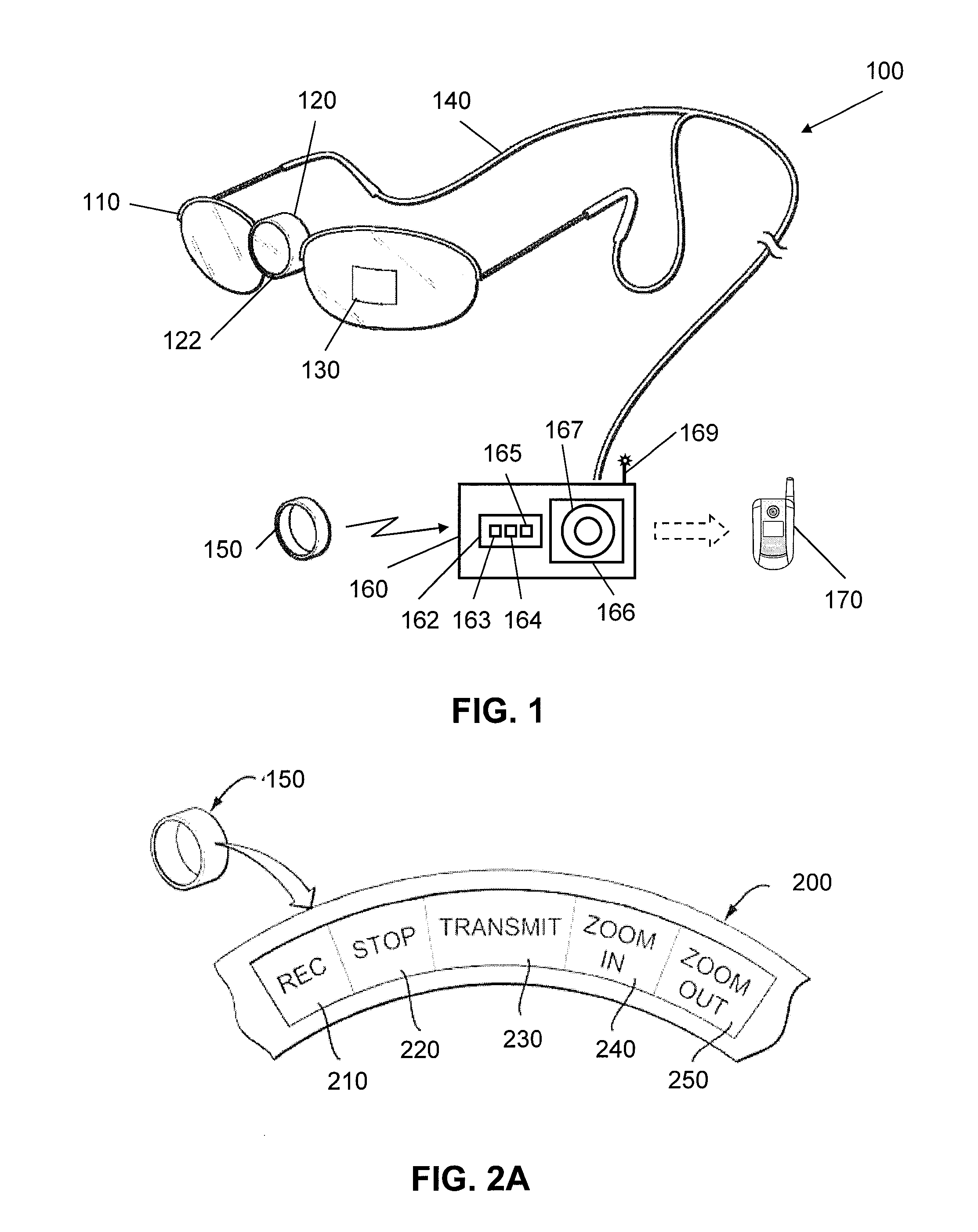
[0019]In FIG. 1, an example surveillance apparatus 100 generally comprising eyeglasses 110 having a camera 120 mounted at the nose bridge, and an optional viewfinder 130 applied onto one of the lenses. A data and power cord 140 couples the camera 120 to a belt-worn recorder 160, which cooperates with a ring-shaped signaling device 150 and a remote memory 170. Those skilled in the art will appreciate that the term “surveillance” is used herein in its broadest possible sense, to include not only professional or commercial types of surveillance, but also any other type of observation, including for example an ordinary person watching a baseball game or birthday party.

[0020]The eyeglasses 110 are used here euphemistically to represent any type of camera mount. In a preferred embodiment, the camera mount is disguised to be a common object worn by a person or lying around a house, but could also be shaped and sized to look like a camera. Contemplated mounts include lapel pins, hair clips,...


PUM


Abstract

A surveillance apparatus continuously records imaged data from a camera into a circular buffer in a local memory. When a record signal is received, the system records the video stream that was recorded before the record signal was received, and the video stream that is recorded after the record signal was received. The recorded segment is then write-protected, so that the surveillance apparatus does not overwrite the recorded segment. The recorded segment could then be sent to a remote memory via a wireless connection to free up local memory for future recording sessions.

Description

[0001]This application is a continuation-in-part of U.S. patent application Ser. No. 11 / 770,920, filed Jun. 29, 2007, which claims the benefit of U.S. provisional patent 60 / 824,097, filed Aug. 31, 2006, and this application is a continuation-in-part of U.S. patent application Ser. No. 11 / 846,217, filed Aug. 28, 2007, which claims the benefit of U.S. provisional patent 60 / 824,095, filed Aug. 31, 2006. These and all other referenced extrinsic materials are incorporated herein by reference in their entirety. Where a definition or use of a term in an incorporated reference is inconsistent or contrary to the definition of that term provided herein, the definition of that term provided herein applies and the definition of that term in the reference does not apply.I. FIELD OF THE INVENTION[0002]The field of the invention is video camera recording technology.II. BACKGROUND[0003]Conventional camcorders use a variety of storage formats including digital video cassettes, mini-DV cassettes, or ...

Claims


Application Information

Patent Timeline
Patent Type & Authority Applications(United States)
IPC IPC(8): H04N7/18
CPCH04N7/18G11B23/288G11B27/10G11B31/006G08B13/19676H04N5/76H04N5/77G08B15/001G08B13/19621G11B2220/216H04N1/00127H04N23/661
Inventor DEKEYSER, PAUL
Owner STELLAR
Why Eureka
Try Eureka