
Data buffer structure for physical and transport channels in a CDMA system

a data buffer and physical and transport channel technology, applied in the field of data communication, can solve the problems of long processing delay and inefficiency, and achieve the effects of reducing or eliminating the amount of fragmentation in the buffer, and efficient storage of symbols received

Inactive Publication Date: 2007-03-06
QUALCOMM INC
View PDF8 Cites 55 Cited by
  • Summary
  • Abstract
  • Description
  • Claims
  • Application Information

AI Technical Summary

Benefits of technology

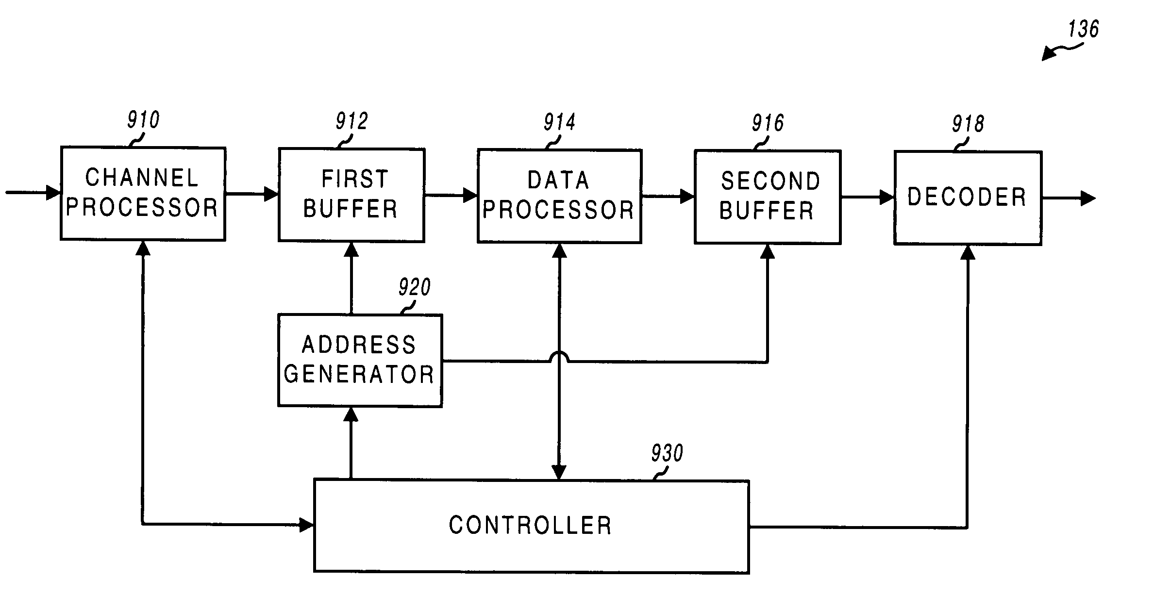
[0009]The present invention provides data buffer structures that can be used to efficiently store symbols received for a number of physical and transport channels. Two buffers can be provided to store symbols received for the physical and transport channels. Each buffer can be partitioned into a number of sections and the sections can be assigned such that the symbols received for each physical or transport channel can be store to a respective assigned section. Each buffer can be partitioned and allocated such that (1) the received and stored symbols are not prematurely overwritten by newly received symbols, (2) the amount of fragmentation in the buffer is reduced or eliminated, and (3) the maintenance and operation of the buffer are simplified.

Problems solved by technology

The IS-95 CDMA systems are able to transmit voice data and (albeit not efficiently) packet data.
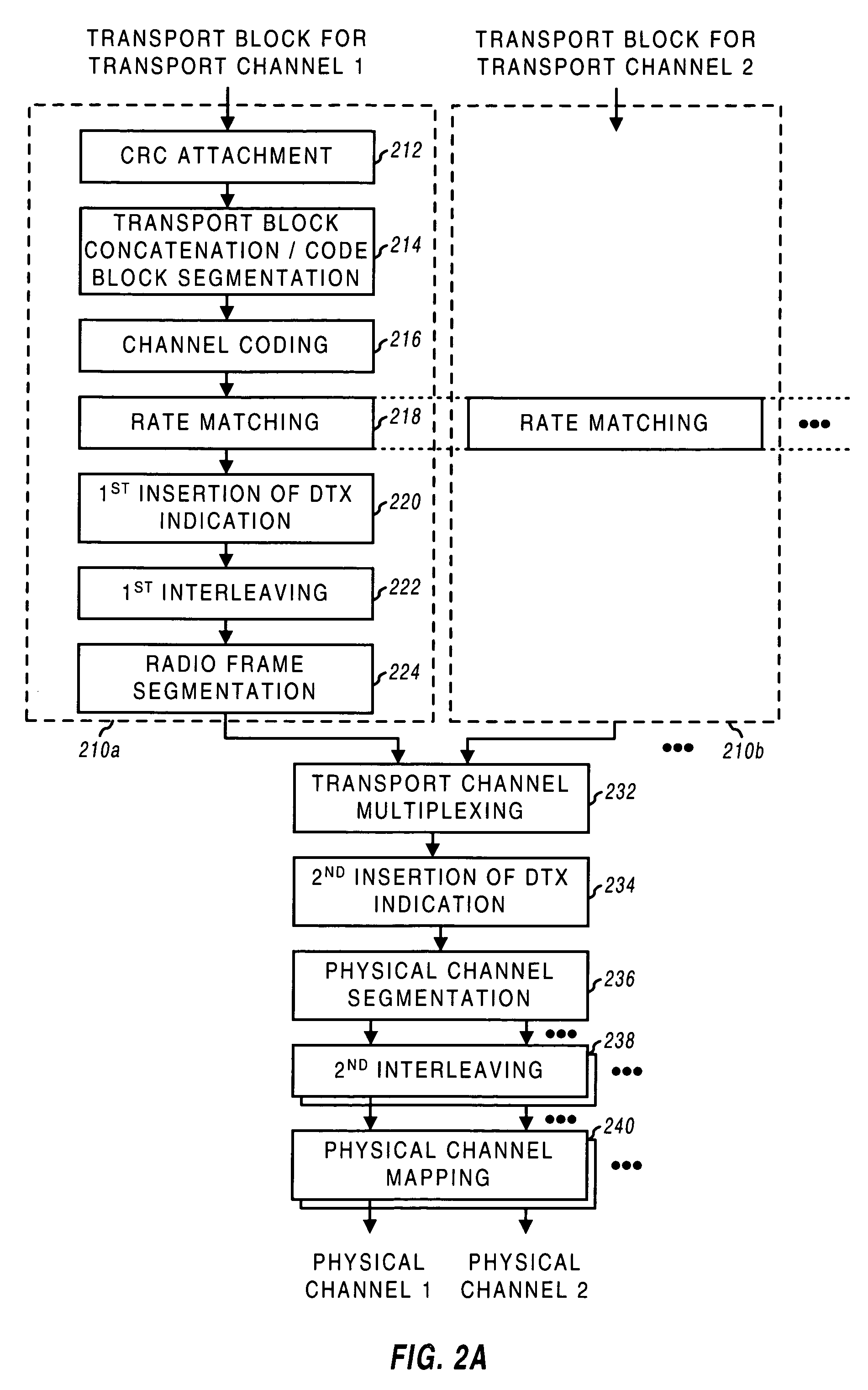
For example, enhanced efficiency and performance may be obtained by processing packet data using Turbo code and a long interleaving interval, which may result in longer processing delays.
In contrast, voice and video data may be processed using convolutional code and a short interleaving interval since long processing delays cannot be tolerated.

Method used


Image

  • Data buffer structure for physical and transport channels in a CDMA system
  • Data buffer structure for physical and transport channels in a CDMA system
  • Data buffer structure for physical and transport channels in a CDMA system

Examples


Embodiment Construction

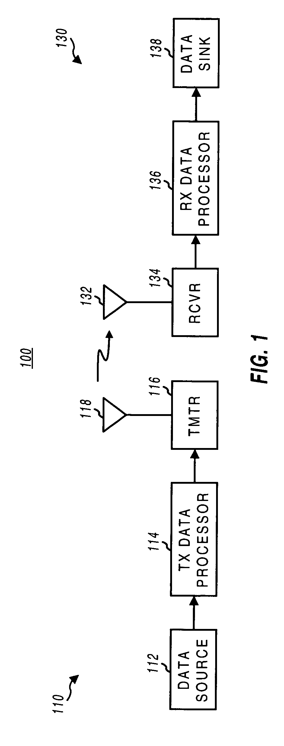
[0023]FIG. 1 is a simplified block diagram of a communication system 100 that can implement the invention. In a specific embodiment, communication system 100 is a CDMA system that conforms to the W-CDMA standard. At a transmitter unit 110, data is sent, typically in blocks, from a data source 112 to a transmit (TX) data processor 114 that formats, codes, and processes the data to generate one or more analog signals. The analog signals are then provided to a transmitter (TMTR) 116 that (quadrature) modulates, filters, amplifies, and upconverts the signal(s) to generate a modulated signal. The modulated signal is then transmitted via one or more antennas 118 (only one is shown in FIG. 1) to one or more receiver units.

[0024]At a receiver unit 130, the transmitted signal is received by one or more antennas 132 (again, only one is shown) and provided to a receiver (RCVR) 134. Within receiver 134, the received signal(s) are amplified, filtered, downconverted, (quadrature) demodulated, and...


PUM


Abstract

A buffer structure for storing symbols received via a number of (e.g., physical or transport) channels. Each channel is associated with a particular time interval (e.g., a radio frame period or a transmission time interval (TTI)) over which the received symbols are processed (e.g., interleaved). The buffer structure includes a buffer and an address generator. The buffer is partitioned into a number of sections. One section is assigned to each channel being processed. Each section can be operated as a circular buffer. The address generator provides addresses for writing symbols to the assigned sections. If the buffer structure is used for the transport channels, the sections can be assigned to the transport channels based on the associated TTIs (e.g., in descending order of TTIs). For each coded composite transport channel (CCTrCH), the transport channels in the CCTrCH can be assigned to sections defined starting from a respective initial location (e.g., the top or bottom of the buffer) and continuing along a respective direction of the buffer (e.g., downward or upward).

Description

BACKGROUND OF THE INVENTION[0001]I. Field of the Invention[0002]The present invention relates to data communication. More particularly, the present invention relates to a novel and improved data buffer structures for storing symbols received for multiple physical and transport channels in a CDMA system.[0003]II. Description of the Related Art[0004]A modern day communication system is required to support a variety of applications. One such communication system is a code division multiple access (CDMA) system that supports voice and data communication between users over a terrestrial link. The use of CDMA techniques in a multiple access communication system is disclosed in U.S. Pat. No. 4,901,307, entitled “SPREAD SPECTRUM MULTIPLE ACCESS COMMUNICATION SYSTEM USING SATELLITE OR TERRESTRIAL REPEATERS,” and U.S. Pat. No. 5,103,459, entitled “SYSTEM AND METHOD FOR GENERATING WAVEFORMS IN A CDMA CELLULAR TELEPHONE SYSTEM,” both assigned to the assignee of the present invention and incorpo...

Claims


Application Information

Patent Timeline
IPC IPC(8): H04B1/69H04B1/707
CPCH04B1/707H04B2201/70703
Inventor SHIU, DA-SHANAGRAWAL, AVNEESH
Owner QUALCOMM INC
Learn More