Light emitting device and lighting device having the same

a technology of light emitting device and lighting device, which is applied in the direction of lighting and heating apparatus, semiconductor devices for light sources, instruments, etc., can solve the problems of unsatisfactory light-emitting device b>100/b> in the view of obtaining and become harder to obtain the higher scattering ability. , to achieve the effect of higher scattering ability

Active Publication Date: 2009-02-26
SHARP KK +1
View PDF10 Cites 76 Cited by
  • Summary
  • Abstract
  • Description
  • Claims
  • Application Information

AI Technical Summary

Benefits of technology

[0024]The present invention is made in the view of the problem, and an object of the invention is to realize a light-emitting device that (i) scatters light without generating uneven brightness on a liquid crystal display panel and (ii) has higher scattering ability that is obtained by decreasing a reflectance caused by the Fresnel's reflection.

Problems solved by technology

However, the aforesaid conventional lighting devices cause the following problems, respectively.
As such, it becomes harder to obtain the higher scattering ability.
Thus, uneven brightness is generated.
However, under such a requirement, there may be a case where the light-emitting device 100 is unsatisfactory in the view of obtaining the higher scattering ability.
That is, there may be a case where it is unsatisfactory, in the view of obtaining the larger scattering ability, to simply form the light flux controlling member in the shape in which the value of the φ2 / φ1 gradually decreases as φ1 increases.
However, this arrangement has a lens that is remarkably large, thus not being practical.
In this case, it gets darker on the light axes of the light flux controlling members, causing spot-like uneven brightness.

Method used


Image

  • Light emitting device and lighting device having the same
  • Light emitting device and lighting device having the same
  • Light emitting device and lighting device having the same

Examples


embodiment 1

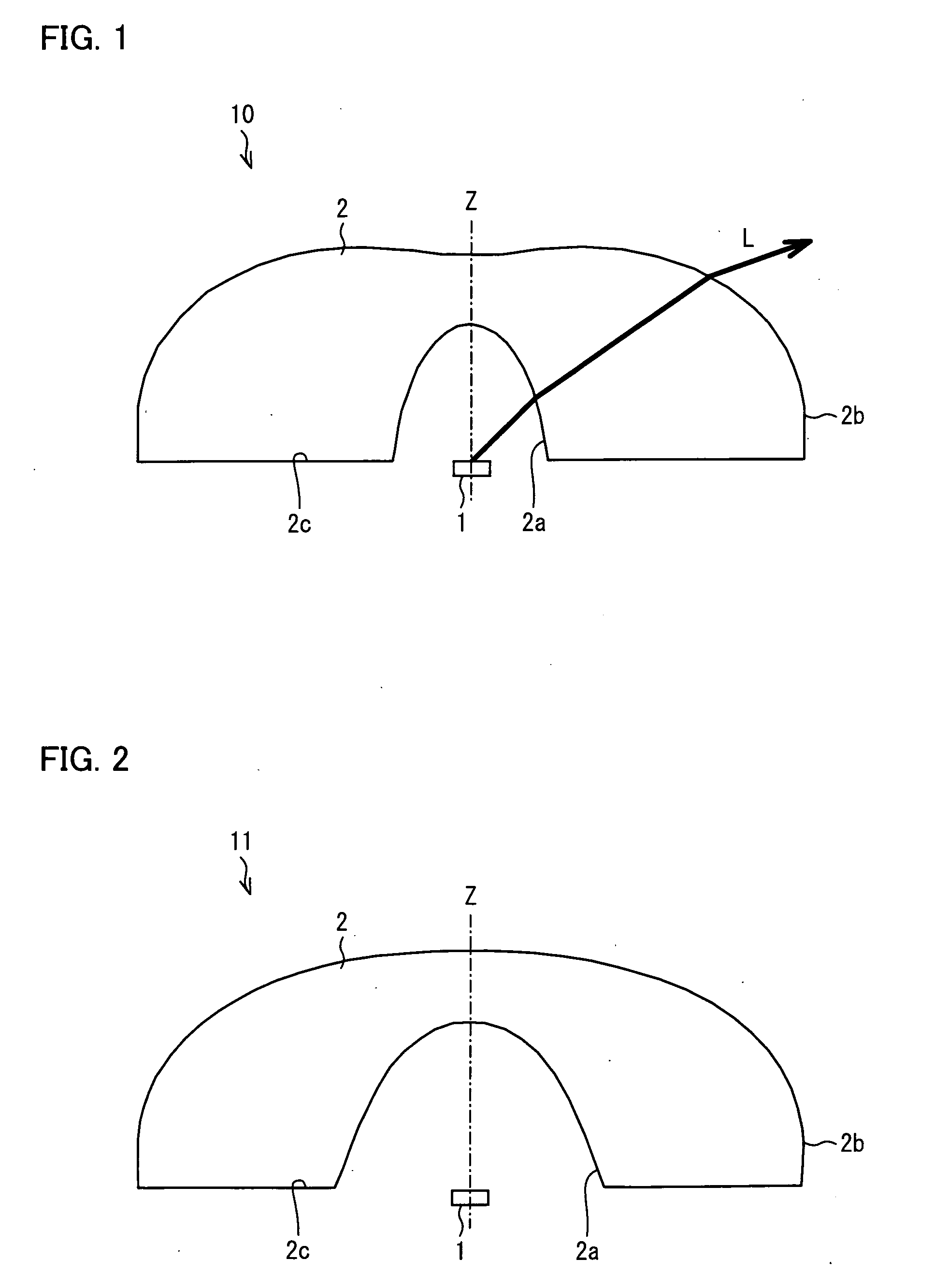
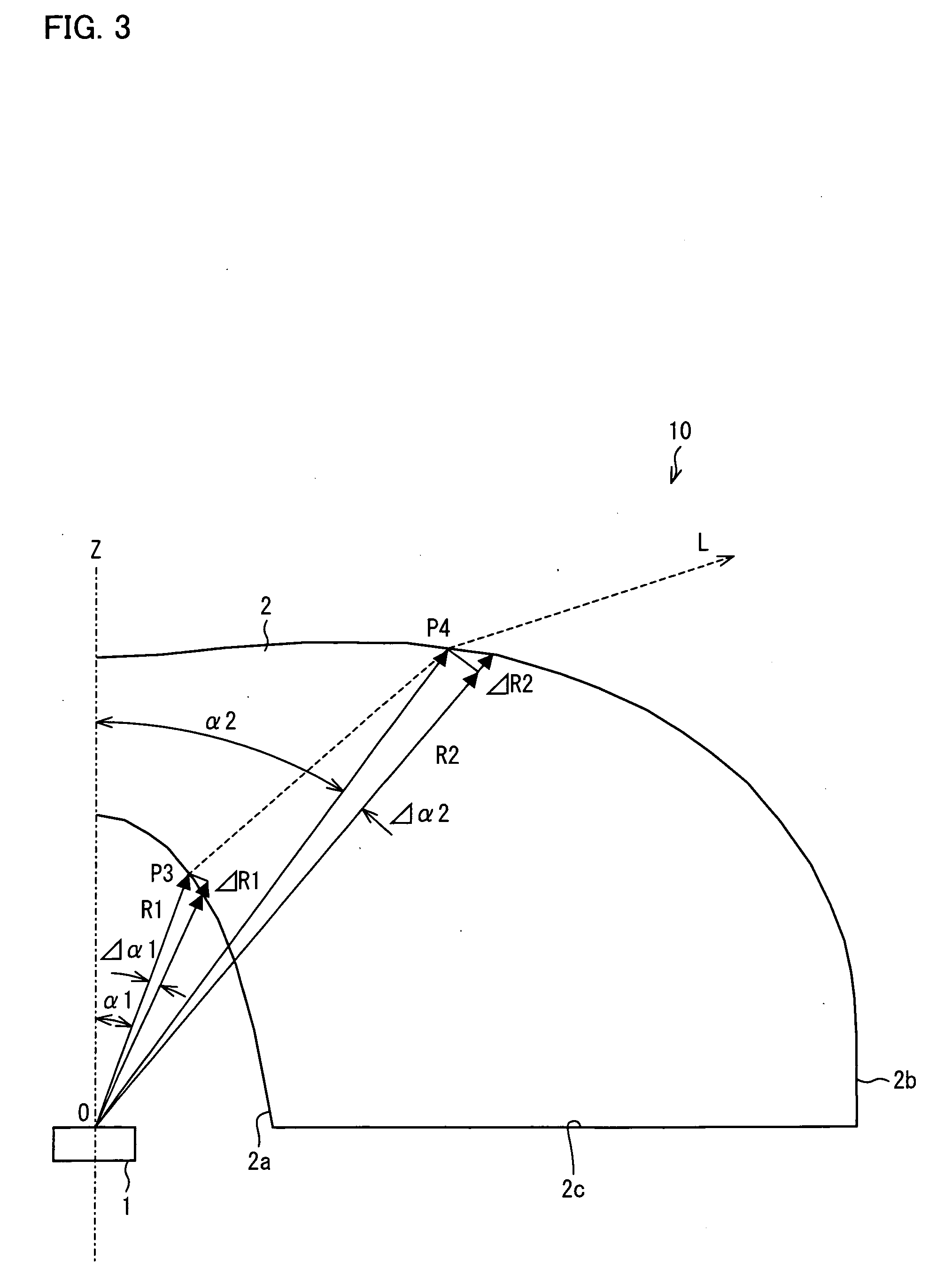
[0049]One embodiment of the present invention is described below with reference to FIGS. 1 through 9. FIG. 1 is a cross-sectional view illustrating a light-emitting device 10 in accordance with the present embodiment. The light-emitting device illustrated in FIG. 1 includes a light-emitting element 1 and a light flux controlling member 2 arranged to surround and cover the light-emitting element 1. A direction of a light axis Z (a reference light axis) indicates a direction in which light proceeds three-dimensionally at a center of an outgoing light flux of light that is emitted from the light-emitting element 1. For convenience, in FIG. 1, a direction vertical to the light-emitting element 1 is set as the light axis (the reference light axis) Z.

[0050]Furthermore, the light-emitting device 10 has a rotation-symmetrical shape with respect to the light axis Z. However, the light-emitting element 1 does not necessarily have a rotation-symmetrical shape. Alternatively, the light-emitting...

embodiment 2

[0081]The following describes another embodiment in accordance with the present invention, with reference to FIGS. 10 through 12. An arrangement other than described in the present embodiment is the same as that described in Embodiment 1. For an easy explanation, members having the same functions as those shown in figures in Embodiment 1 are given the same reference numerals, and explanations thereof are omitted.

[0082]FIG. 10 is a cross-sectional view of a light-emitting device 10 in accordance with the present embodiment. In the light-emitting device illustrated in FIG. 10, a light-emitting element 1 and a light flux controlling member 2 are provided with a certain distance therebetween. In such an arrangement, a part of light emitted from a light-emitting element 1 may directly enter a bottom surface 2c, without entering a light-incoming surface 2a. Subsequently, the light is transmitted through the light flux controlling member 2; is condensed on a light-outgoing surface 2b; and,...

embodiment 3

[0090]The following describes yet another embodiment in accordance with the present invention, with reference to FIGS. 13 through 18. Arrangements other than described in the present embodiment are the same as those described in Embodiment 1. For convenience, members having the same functions as those shown in the figures in Embodiment 1 are given the same reference numerals, and explanations thereof are omitted.

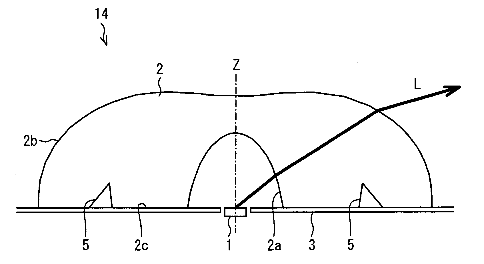
[0091]FIG. 13 is a cross-sectional view of a light-emitting device 14 in accordance with the present embodiment. The light-emitting device 14 includes a light scattering section 5 of a cuneal shape on a bottom surface 2c. The light scattering section 5 is not limited to a particular kind, provided that the light scattering section 5 (i) reflects light in a same manner as a bezel of a prism having a cuneal shape or the like and (ii) deflects a light direction almost perpendicular to the light axis Z. In FIG. 13, the light scattering section 5 has a rotationally symmetrical sh...


PUM


Abstract

A light-emitting device (10) is arranged such that (x) R1 monotonically decreasing as α1 increases, at least in a range of α1<π / 3, where an intersection of a light axis Z and an emission surface of a light-emitting element (1) is a reference point; α1 is an angle between the light axis Z and a straight line that passes through the reference point and an arbitrary point on a light-incoming surface (2a), and R1 is a distance between the reference point and the arbitrary point on the light-incoming surface (2a); (y) R2 monotonically increasing as α2 increases, at least in a range of α2<π / 3, where α2 is an angle between the light axis Z and a straight line that passes through the reference point and an arbitrary point on a light-outgoing surface (2b), and R2 is a distance between the reference point and the arbitrary point on the light-outgoing surface (2b); and (z) A2 scatters light without generating uneven brightness on a liquid crystal display panel and has higher scattering ability that is obtained by decreasing a reflectance caused by the Fresnel reflection, where n is a refraction index of a material forming a light flux controlling member (2), and A2=ΔR2 / (R2Δα2), where ΔR2 is an increment of R2 and Δα2 is an increment of α2.

Description

[0001]This Nonprovisional application claims priority under 35 U.S.C. § 119(a) on Patent Application No. 208656 / 2007 filed in Japan on Aug. 9, 2007, the entire contents of which are hereby incorporated by reference.FIELD OF THE INVENTION[0002]The present invention relates to a light-emitting device and a lighting device having the same, and more particularly, relates to: a light-emitting device (i) having a light flux controlling member and a lighting device having this light-emitting device, which are capable of being used as, for example, a light source for use in a backlight that performs planar irradiation to a liquid crystal display panel from a back surface side of the liquid crystal display panel and an ordinal interior lighting.BACKGROUND OF THE INVENTION[0003]Conventionally, it has been known to use a surface light source device using plural light-emitting diodes (hereafter, referred to as “LED,” as appropriate) as lighting means for irradiating a liquid crystal display mon...

Claims


Application Information

Patent Timeline
Patent Type & Authority Applications(United States)
IPC IPC(8): F21V5/00F21S2/00H01L33/58F21Y101/02G02B3/02G02B13/18H01L33/00H01L33/48
CPCH01L33/58F21W2131/103G02B19/0061F21Y2101/02G02B19/0014F21V5/048F21Y2115/10G02F1/1335
Inventor KOKUBO, FUMIOYAMAGUCHI, MASAO
Owner SHARP KK
Why Eureka
Try Eureka