
Light source unit, optical scan apparatus, and image formation apparatus

a light source and optical scan technology, applied in the direction of electrographic process apparatus, instruments, printing, etc., can solve the problems of significant deterioration of image quality, positional difference, and uneven height of the mounted light emission portion, and achieve the effect of stably forming high-quality images

Active Publication Date: 2009-02-26
RICOH KK
View PDF99 Cites 43 Cited by
  • Summary
  • Abstract
  • Description
  • Claims
  • Application Information

AI Technical Summary

Benefits of technology

[0013]In view of solving the above problems, an object of the present invention is to provide a light source unit in which a light source can be precisely positioned relative to an optical system at three places, so as to stably form high quality images, as well as to provide an optical scan apparatus incorporating such a light source unit and an image formation apparatus incorporating such an optical scan apparatus.

Problems solved by technology

For mounting the light emission portions on a circuit board by soldering, the mounted light emission portions are not uniform in height.
In this case, there will be a problem that the positional difference between each light emission portion and the circuit board surface leads to a positional difference between the optical elements and each light emission portion.
With a low precision, beam spot sizes or pitches of light illuminating photoconductive drums are adversely affected, resulting in significantly deteriorating image quality.
However, such a method still has a problem that enforcedly bending the circuit board causes solder of electric components mounted thereon to be peeled off, which may adversely accelerate deterioration of the laser unit over time, for example.
Furthermore, there is another problem in fixation of the light emission portions that since they are fixed to the package by an epoxy adhesive or the like, it is hard to precisely position them on the package even by use of a jig or the like.
It is not possible to accurately set the position of the light source relative to the optical system.

Method used


Image

  • Light source unit, optical scan apparatus, and image formation apparatus
  • Light source unit, optical scan apparatus, and image formation apparatus
  • Light source unit, optical scan apparatus, and image formation apparatus

Examples


first embodiment

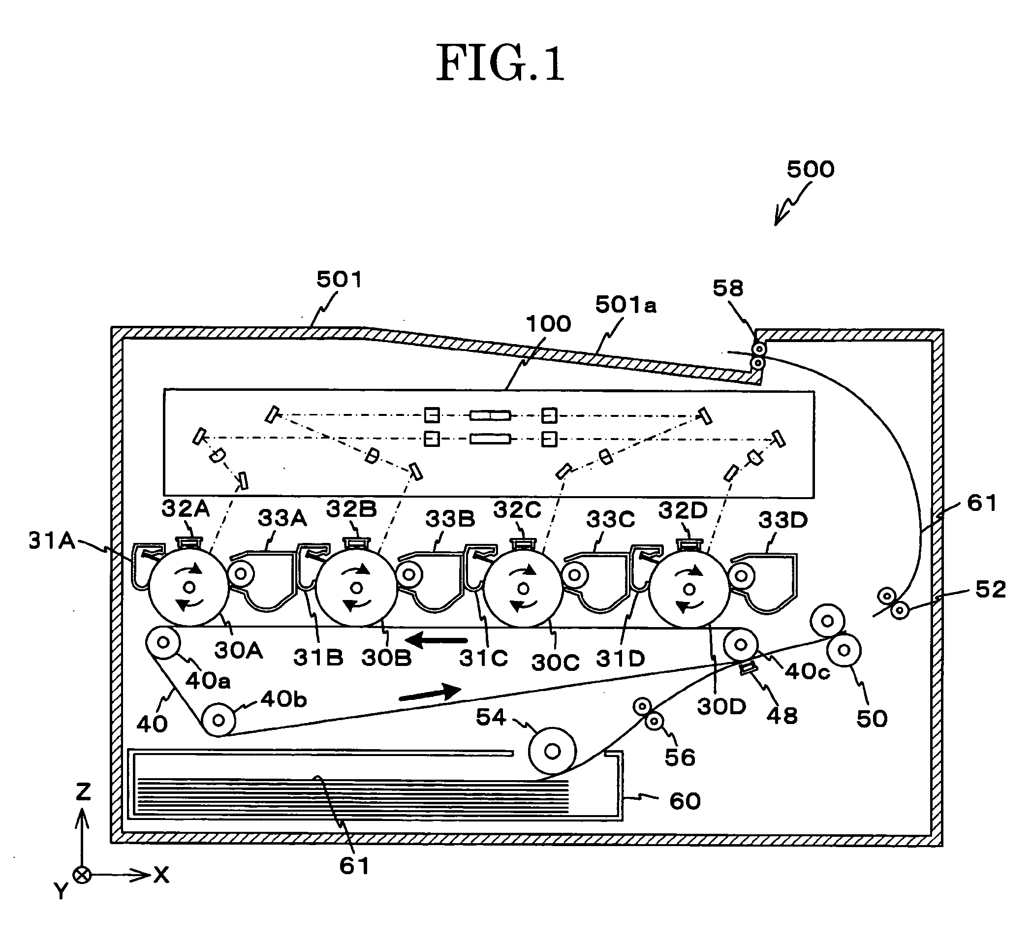
[0057]Hereinafter, the first embodiment of the present invention will be described in detail with reference to FIGS. 1 to 9. FIG. 1 shows an image formation apparatus 500 according to the present embodiment.

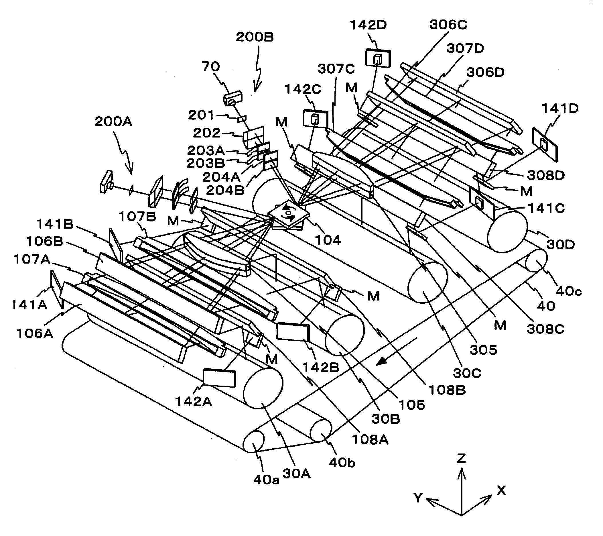
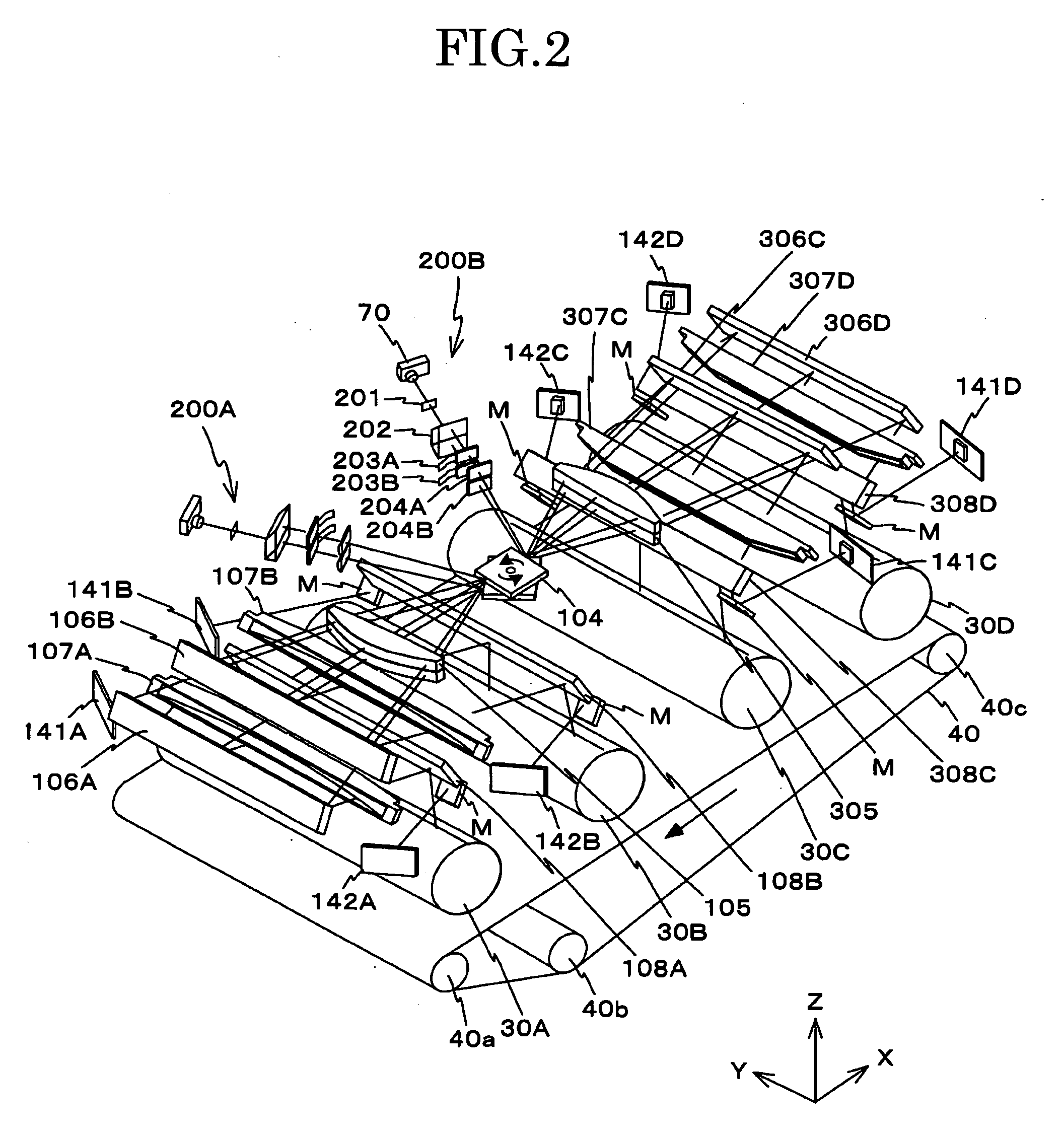
[0058]The image formation apparatus 500 is, for example, a tandem type color printer which prints multi-color images by superimposing and transferring black, yellow, magenta, and cyan color toner images onto sheets of paper. The image formation apparatus 500 as shown in FIG. 1 comprises an optical scan apparatus 100, four photoconductive drums 30A to 30D, a transfer belt 40, a paper feed tray 60, a paper feed roller 54, a first resist roller 56, a second resist roller 52, a fuse roller 50, a paper discharge roller 58, a not-shown controller collectively controlling the respective components, and a housing 501 in rectangular solid shape accommodating the components.

[0059]A paper discharge tray 501a on which printed sheets are discharged is formed on the top surface of the housing ...

second embodiment

[0121]Next, the second embodiment of the present invention will be described with reference to FIGS. 10 to 14. A description on the same components as those in the first embodiment will be simplified or omitted

[0122]FIG. 10 shows a light source unit 70′ according to the second embodiment. The light source unit 70′ is different from the light source unit 70 in that the substrate 76 and the first support portion 74 are joined by use of a pair of holding members 81, 82.

[0123]FIG. 11A perspectively shows the holding member 81 while FIG. 11B partially shows a side thereof. The holding member 81 is formed by press working or sheet metal processing on a metal plate. The holding member 81 is composed of three parts, a rectangular fixation portion 81a which is long in the z-axis direction, a plate-like latch portion 81c with a V-form notch (engaging portion) 81d from an upper end to the center, a connection portion 81b to connect the fixation portion 81a and the latch portion 81c when they a...

third embodiment

[0140]FIG. 17 shows an optical scan apparatus scanning four image formation stations according to the present embodiment. FIG. 17 shows photoconductive drums 1101 to 1104, a polygon mirror 1106, light source units 1107, 1109, beam splitter prisms 1108, 1110, cylindrical lenses 1113 to 1116, liquid crystal elements 1117, 1118, and others. The other components will be described later when appropriate.

[0141]The optical scan apparatus in FIG. 17 is integrally structured to emit a plurality of light beams from the light source units 1107, 1109, and deflect them by the single polygon mirror 1106 to scan the photoconductive drums 1101 to 1104. The photoconductive drums 1101 to 1104 are disposed with equal interval in a moving direction 1105 of a transfer body. Color images are formed by sequentially transferring and superimposing toner images of four different colors formed on the photoconductive drums 1101 to 1104.

[0142]The polygon mirror 1106 is formed in two upper and lower stages to sc...


PUM


Abstract

A light source unit is provided, which includes a light source with a plurality of light emission portions two-dimensionally arranged; a substrate on which the light source is mounted; a first support portion supporting the substrate; a bias member biasing the substrate towards the first support portion; a coupling element coupling a light beam emitted from the light source; a second support portion supporting the coupling element; a holding member holding a position of the substrate relative to the first support portion, a fitting portion provided in each of the first and second support portions to rotatably fit the first and second support portions into each other around an optical axis of the light source; and a fastening member integrally fastening the first and second support portions.

Description

CROSS-REFERENCE TO RELATED APPLICATION[0001]The present application is based on and claims priority from Japanese Patent Application No. 2007-213915, filed on Aug. 20, 2007, No. 2007-226178, filed on Aug. 31, 2007, and No. 2008-82308, filed on Mar. 27, 2008, the disclosure of which is hereby incorporated by reference in its entirety.BACKGROUND OF THE INVENTION[0002]1. Field of the Invention[0003]The present invention relates to a light source unit emitting a light beam, an optical scan apparatus scanning a scan surface with a plurality of light beams and an image formation apparatus incorporating such an optical scan apparatus.[0004]2. Description of Related Art[0005]In the prior art, an image formation apparatus forming images by Carlson process is known. For example, Japanese Laid-open Patent Application Publication No. 2002-341273 discloses such an image formation apparatus which scans the surface of a rotating photoconductive drum with a light beam to form an electrostatic laten...

Claims


Application Information

Patent Timeline
Patent Type & Authority Applications(United States)
IPC IPC(8): G03G15/04
CPCB41J2/473G02B26/123G03G15/0435G03G15/326G02B26/127
Inventor KUBO, NOBUAKINAKAJIMA, TOMOHIROAMADA, TAKUHAYASHI, YOSHINORI
Owner RICOH KK
Features
  • Generate Ideas
  • Intellectual Property
  • Life Sciences
  • Materials
  • Tech Scout
  • Unparalleled Data Quality
  • Higher Quality Content
  • 60% Fewer Hallucinations
Learn More