Fuel cell

a fuel cell and cell technology, applied in the field of fuel cells, can solve the problems of decrepitation of the internal environment of the gas flow path, the degradation and the decrease of the performance of the fuel cell

Active Publication Date: 2009-02-26
PANASONIC CORP
View PDF2 Cites 9 Cited by
  • Summary
  • Abstract
  • Description
  • Claims
  • Application Information

AI Technical Summary

Benefits of technology

[0029]The invention is constructed as described above and therefore achieves the effect of providing subs...

Problems solved by technology

In the areas where the reaction gas is short, the polarization of the electrode reaction increases resulting in degradation of the performance of the fuel cell.
Further, the water produced by the electrode reaction makes the internal environment of the gas flow pa...

Method used


Image

  • Fuel cell
  • Fuel cell
  • Fuel cell

Examples


first embodiment

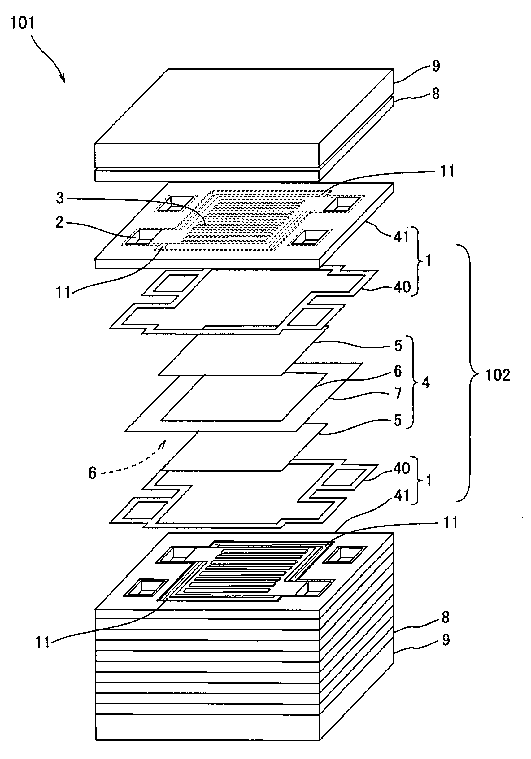
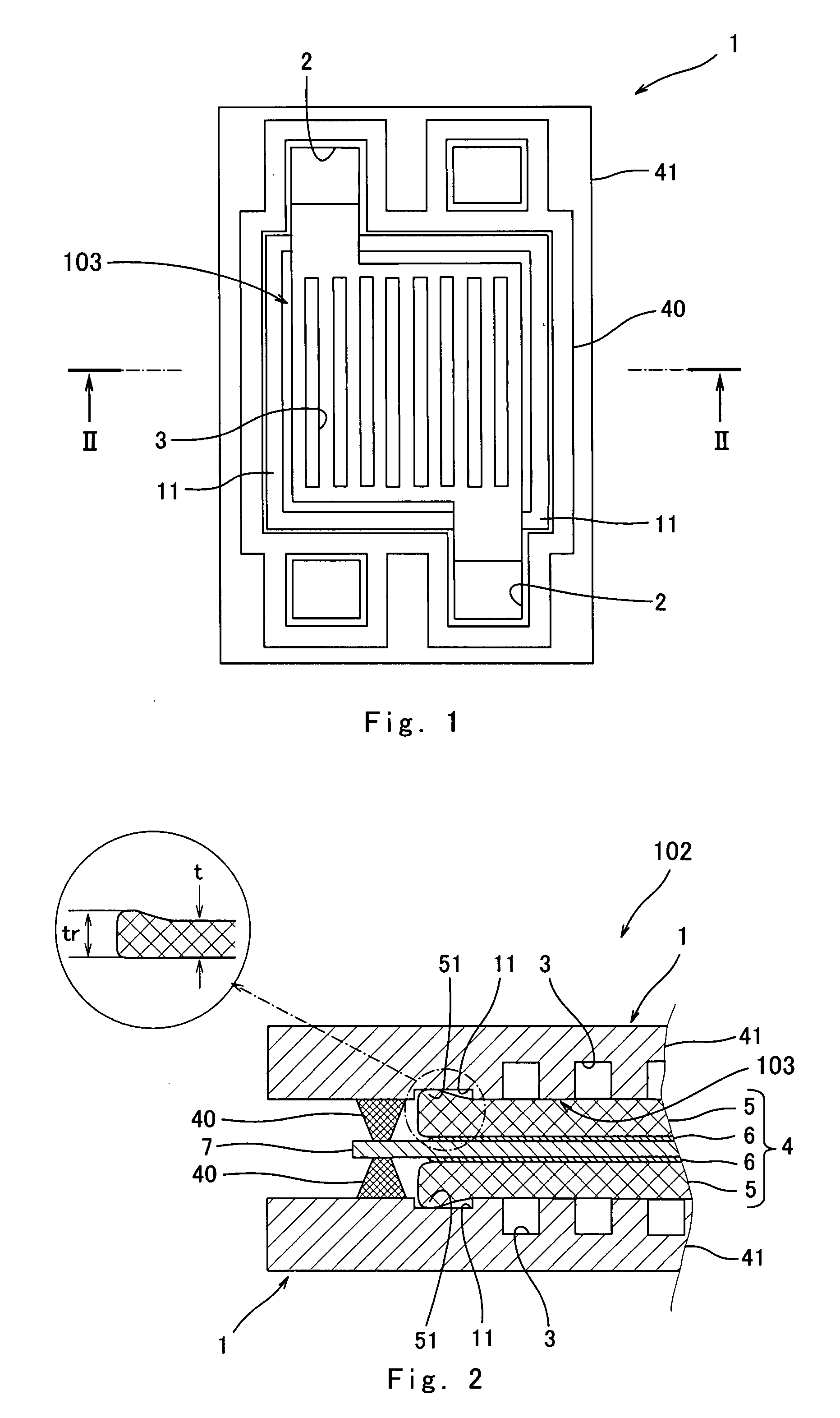
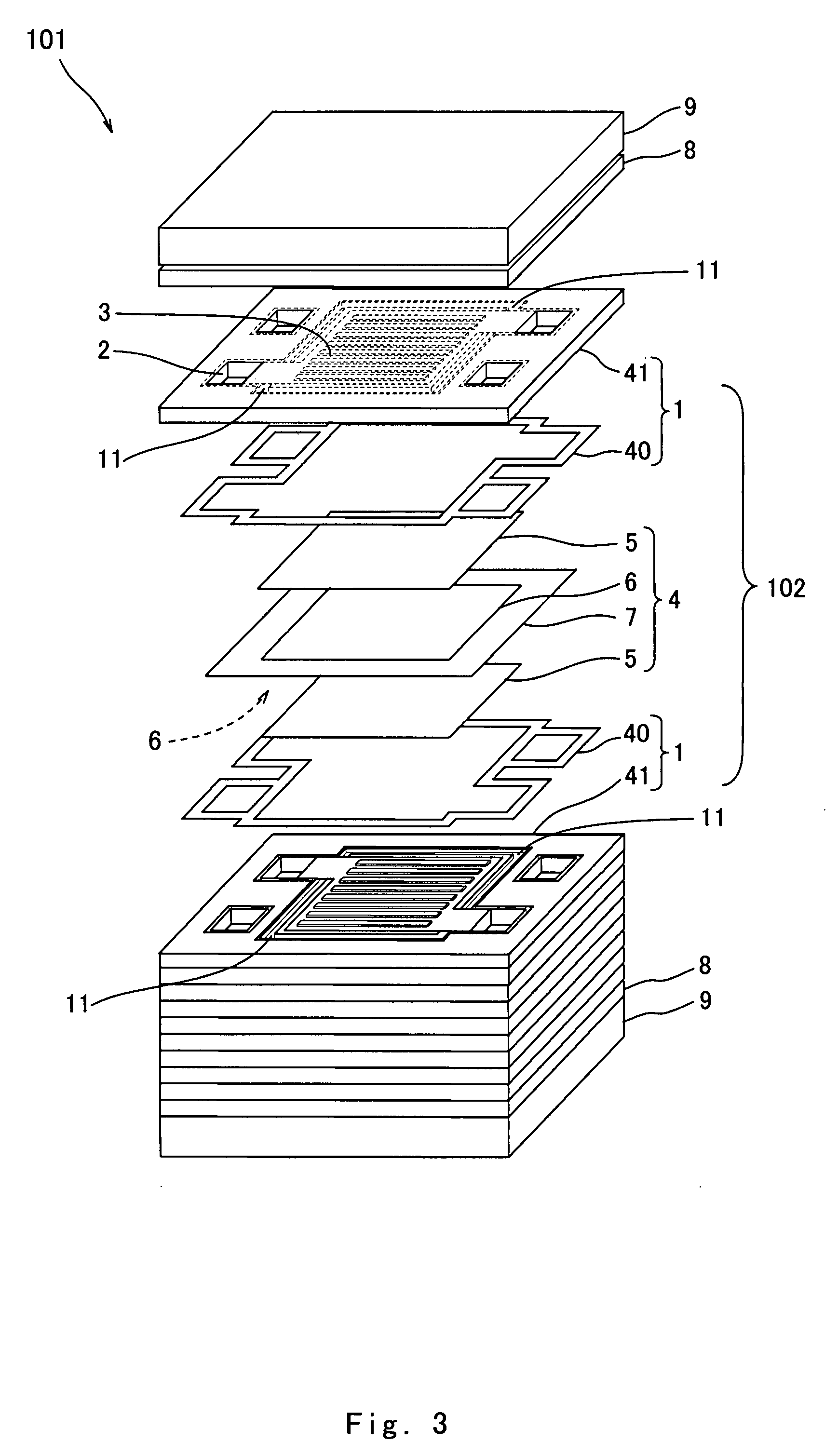
[0080]FIG. 1 is a plan view showing the configuration of a separator for use in a fuel cell according to a first embodiment of the invention. FIG. 2 is a fragmentary sectional view that shows the configuration of a cell used in the fuel cell of the first embodiment of the invention when cut so as to cut the separator along line II-II of FIG. 1. FIG. 3 is an exploded perspective view showing the configuration of the fuel cell of the first embodiment of the invention.

[0081]As illustrated in FIGS. 1, 2, the fuel cell of the first embodiment is equipped with self-sealing separators 1. Each of the self-sealing separators 1 has a separating part 41 and a sealing part 40 formed in the separating part 41. The separating part 41 corresponds to a so-called separator and has the shape of a rectangular plate. One (hereinafter referred to as “inner surface”) of the main surfaces of the separating part 41 is provided with the sealing part 40 constituted by an ordinary sealing member (which is a g...

second embodiment

[0098]FIG. 4 is a plan view showing the configuration of a separator for use in a fuel cell according to a second embodiment of the invention. FIG. 5 is a fragmentary sectional view that shows a cell used in the fuel cell of the second embodiment of the invention when cut so as to cut the separator along line V-V of FIG. 4. In FIGS. 4, 5, those parts similar or corresponding to the parts of FIGS. 1, 2 are identified by the same reference numerals and explanations thereof are omitted herein.

[0099]As illustrated in FIGS. 4, 5, in the second embodiment, a groove (lower area) 11a corresponding to the groove that constitutes the raised portion accommodating area 11 of the first embodiment and an elastic filler 12 filling the groove 11a constitute the raised portion accommodating area 11. Formed on the surface of the elastic filler 12 is a recessed part 12a. The recessed part 12a is shaped so as to just receive the raised portion 51 of the gas diffusion layer 5 of the MEA 4. In other word...

third embodiment

[0107]FIG. 6 is a fragmentary sectional view that shows a cell used in a fuel cell according to a third embodiment of the invention. In FIG. 6, those parts similar or corresponding to the parts of FIG. 5 are identified by the same reference numerals and explanations thereof are omitted herein.

[0108]As illustrated in FIG. 6, in the third embodiment, the raised portion accommodating area 11 of each self-sealing separator 1 is constituted by the groove (lower area) 11a that is the same as that in the second embodiment and an elastic film 13 that is formed so as to extend over the opening of the groove 11a. Although the elastic film 13 is made of a rubber material such as fluoro rubber, silicon rubber or ethylene-propylene rubber (EPDM), the material of the elastic film 13 is not limited to any particular material as long as it is deformed when depressed by the raised portion 51 of the gas diffusion layer 5. Except this point, the third embodiment does not differ from the second embodim...


PUM


Abstract

The invention provides a fuel cell comprising one or more cells (102) stacked therein, each of the cells (102) including:
    • an MEA (4) having a polymer electrolyte membrane (7) and a pair of gas diffusion layers (5) sandwiching the polymer electrolyte membrane (7) except a peripheral region of the polymer electrolyte membrane (7); and
    • a pair of self-sealing separators (1) disposed so as to sandwich the MEA (4), each of the self-sealing separators (1) being formed in a plate-like shape as a whole and composed of a separating part (41) having electrical conductivity and a sealing part (40) having more elasticity than the separating part (41), at least the separating part (41) being in contact with an associated one of the gas diffusion layers (5), the sealing part (40) being in contact with the peripheral region of the polymer electrolyte membrane (7) so as to enclose the associated one of the gas diffusion layers (5),
    • wherein each self-sealing separator (1) has a lower area (11) for accommodating a raised portion (51) formed on the periphery of the outer surface of the associated gas diffusion layer (5) and the sealing part (40) is disposed within the lower area (11).

Description

TECHNICAL FIELD[0001]The present invention relates to a fuel cell well suited for use in portable power sources, electric vehicle batteries, domestic cogeneration systems and others. More particularly, the present invention relates to a fuel cell having a polymer electrolyte membrane.BACKGROUND ART[0002]Polymer electrolyte fuel cells are conventionally well known. Polymer electrolyte fuel cells include an anode and a cathode which consist of catalyst reaction layers and gas diffusion layers respectively and are arranged so as to hold a polymer electrolyte membrane therebetween. A hydrogen-containing fuel gas and an oxygen-containing oxidizing gas, such as air, (the fuel gas and oxidizing gas are hereinafter generically called as “reaction gases”) are supplied to the anode and the cathode. In the anode, electrons are released from the hydrogen atoms contained in the fuel gas through an electrode reaction thereby generating hydrogen ions and these electrons reach the cathode by way of...

Claims


Application Information

Patent Timeline
IPC IPC(8): H01M8/10
CPCH01M8/0247H01M8/0276Y02E60/50H01M2008/1095H01M8/242H01M8/0273H01M8/0271H01M8/241
Inventor SHIBATA, SOICHIKUSAKABE, HIROKIHATOH, KAZUHITO
Owner PANASONIC CORP
Why Eureka
Try Eureka